
C2DTD: A Physics-Informed Digital Fingerprint to Accelerate Carbon Materials
Researchers developed the CARBON-2D Topological Descriptor (C2DTD), an interpretable, physics-informed method to rapidly predict the properties of new 2D...
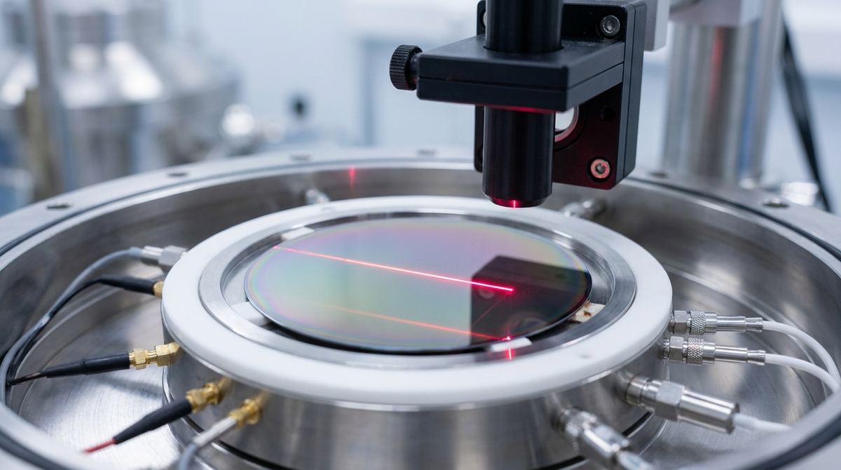
The promise of graphene in next-generation electronics hinges on our ability to control its electronic properties with precision. Unlike silicon, graphene has no natural bandgap and is intrinsically neutral. To create useful components like diodes and transistors, we must introduce charge carriers, a process called doping, to create n-type (excess electrons) and p-type (electron-deficient) regions. Traditional methods often involve surface contaminants or complex gating structures, which can degrade performance and complicate manufacturing.
A recent study offers a more elegant solution, leveraging the substrate itself to control graphene's doping profile. By growing graphene on a germanium-on-silicon wafer, a standard platform in the semiconductor industry, researchers have uncovered a mechanism to switch the graphene from n-type to p-type simply by controlling the oxidation state of the underlying germanium. This guide translates that fundamental discovery into a practical engineering project: fabricating a simple graphene p-n junction diode by selectively oxidizing the substrate. This approach could pave the way for simpler, cleaner, and more integrated graphene electronics.
The objective of this project is to fabricate and test a basic p-n junction diode on a single, continuous sheet of graphene. A p-n junction is the fundamental building block of most semiconductor devices. It allows current to flow easily in one direction (forward bias) but restricts its flow in the opposite direction (reverse bias).
We will achieve this by creating adjacent p-type and n-type regions within the same graphene layer. The n-type region will be the graphene in its as-grown state on pristine germanium. The p-type region will be created by intentionally and selectively oxidizing the germanium layer directly beneath the graphene. By depositing metal contacts onto each region, we can then test the electrical characteristics of the junction and verify its diode-like rectifying behavior.
This project is based on the findings of a 2026 paper by Pawel Dabrowski and colleagues, titled "Electronic Coupling and Charge-Transfer Landscape of Graphene on Ge(001)/Si(001)". The research team used a combination of advanced microscopy, spectroscopy, and theoretical modeling to investigate the graphene-germanium interface.
Their key discoveries that enable our project are:
1. Default N-Type Doping: On a clean, pristine Ge(001) surface, electrons naturally transfer from the germanium to the graphene. This charge transfer results in n-type doping, giving the graphene an excess of electron charge carriers.
2. Oxidation-Induced P-Type Doping: The researchers' theoretical models predicted a fascinating reversal. When an oxide layer forms at the graphene-germanium interface, the situation flips. The oxidized germanium becomes electron-withdrawing, pulling electrons out of the graphene. This results in p-type doping, leaving the graphene with an excess of "holes" (electron vacancies).
3. Substrate Morphology: The study also revealed that the Ge(001) surface is not perfectly flat but consists of "nanofacets." This underlying topography creates subtle variations in the graphene's electronic properties. While our project will treat the surface as uniform for simplicity, this is a critical factor to remember when analyzing device performance and considering scalability. The regions on top of nanofacets behave differently from those in the valleys between them.
This ability to switch doping polarity by controlling a single interface parameter—oxidation—is the core mechanism we will exploit. The paper provides the scientific validation; our task is to develop a practical fabrication process based on it.
This is a lab-scale project requiring access to a cleanroom or a well-equipped materials science laboratory.
Materials:
Substrate: One or more Graphene on Ge(001)/Si(001) wafers. These are typically produced via Chemical Vapor Deposition (CVD). The quality of the initial wafer is critical. You can source these from commercial suppliers or use an in-house CVD system. The specifics of the graphene manufacturing techniques used will influence the starting quality.
Chemicals: Standard photolithography chemicals including a positive photoresist (e.g., S1813), developer (e.g., MF-319), acetone, and isopropyl alcohol (IPA).
Metal Targets: High-purity metal targets for contact deposition, such as Titanium (Ti) for an adhesion layer and Gold (Au) or Palladium (Pd) for the contact layer.
Process Gases: High-purity nitrogen (N2) and oxygen (O2) for annealing and processing steps.
Equipment:
Lithography: A spin coater for applying photoresist and a mask aligner or laser writer for patterning. For a cruder first-pass prototype, a simple physical shadow mask could be used.
Oxidation System: A tube furnace with precise temperature and gas flow control is ideal. Alternatively, a UV/Ozone cleaner or a carefully controlled laser system could be used for localized oxidation.
Deposition System: An e-beam or thermal evaporator for depositing the metal contacts.
Characterization Tools:
Raman Spectrometer: Essential for verifying graphene quality (presence of D peak), number of layers (2D peak shape), and doping (shift in G and 2D peak positions).
Atomic Force Microscope (AFM): Useful for imaging the surface morphology and verifying successful resist removal. A Kelvin Probe Force Microscopy (KPFM) module is highly recommended for mapping the work function and directly visualizing the p-n junction.
Probe Station and Semiconductor Parameter Analyzer: Required for the final electrical testing of the diode's current-voltage (I-V) characteristics.
This is a proposed process flow based on the paper's findings. The exact parameters for oxidation (temperature, time, oxygen concentration) are not specified in the source and must be determined experimentally. Always start with cautious parameters to avoid damaging the graphene.
1. Initial Characterization:
Before processing, characterize your starting wafer.
Use Raman spectroscopy at several points to confirm you have high-quality monolayer graphene. Look for a low D/G peak ratio (<0.1) and a sharp, symmetric 2D peak.
Record the initial positions of the G (~1585 cm-1) and 2D (~2680 cm-1) peaks. These will be your baseline for the n-type region.
If available, use KPFM to map the work function of the as-grown graphene. This confirms its initial n-type state.
2. Patterning for Selective Oxidation:
The goal is to protect the areas that will remain n-type.
Spin-coat the entire wafer with a positive photoresist.
Use your mask aligner or laser writer to expose the photoresist in the areas where you want to create p-type graphene.
Develop the resist. The areas to be oxidized should now be exposed, while the future n-type areas remain covered.
3. Controlled Interface Oxidation:
This is the most critical and experimental step. The goal is to oxidize the underlying Ge without damaging the overlying graphene. Graphene is a good barrier, but defects can allow oxygen to penetrate.
Engineering Assumption: A low-temperature thermal anneal is a controllable starting point.
Place the patterned wafer in a tube furnace.
Purge with N2 or Argon.
Slowly ramp the temperature. Start with a very conservative temperature, for example, 200-300°C. Germanium oxide can form at these temperatures.
Introduce a low concentration of O2 (e.g., 1-5% in N2) for a set duration (e.g., 10-30 minutes).
Purge with N2 and cool down slowly.
You will need to run a design of experiments (DOE) to find the optimal temperature, time, and O2 concentration that creates p-type doping without creating significant defects in the graphene.
4. Resist Removal:
After oxidation, strip the remaining photoresist using acetone, followed by a rinse in IPA and a gentle N2 dry.
Inspect the surface with an optical microscope and AFM to ensure all resist residue is gone. Residue can interfere with subsequent steps.
5. Contact Patterning and Deposition:
You now need to deposit metal contacts on both the p-type and n-type regions.
Repeat the photolithography process, this time using a mask that defines the contact pads. This will involve spin-coating, exposing, and developing to create openings in the resist where the metal should be.
Place the wafer in your evaporator.
Deposit an adhesion layer (e.g., 5 nm of Ti) followed by a conductive layer (e.g., 50 nm of Au or Pd).
Perform liftoff by dissolving the remaining photoresist in acetone. This will leave behind only the metal contacts in the desired pattern.
Your final device is a sheet of graphene with two distinct regions (p-type and n-type) and a metal contact on each.
Verification must happen at both the material and device level.
1. Post-Oxidation Material Analysis:
Use Raman spectroscopy again. Map both the protected (n-type) and oxidized (p-type) regions.
In the n-type region, the G and 2D peaks should be close to their original positions.
In the p-type region, you should observe an "up-shift" (increase in wavenumber) for both the G and 2D peaks. This shift is a classic indicator of p-doping.
Crucially, check the D peak in the oxidized region. A significant increase indicates that your oxidation process was too aggressive and created defects in the graphene lattice. The goal is to achieve a doping shift with a minimal increase in the D/G ratio.
Use KPFM to map the surface. You should see a clear contrast in the work function between the two regions, directly visualizing the p-n junction you created. The p-type region should have a higher work function than the n-type region.
2. Device Electrical Testing:
Place the wafer on a probe station.
Connect the probes from your semiconductor parameter analyzer to the contacts on the p-type and n-type regions.
Sweep the voltage (V) across the junction, for example from -2V to +2V, while measuring the current (I).
Plot the I-V curve. If the junction is successful, you will see diode-like rectifying behavior:
In forward bias (positive voltage on the p-type side), the current should increase exponentially once the turn-on voltage is reached.
In reverse bias (negative voltage on the p-type side), the current should be very low (leakage current).
Characterize multiple devices across the wafer to assess uniformity.
This process is promising but not without significant challenges that a small lab or startup must consider.
Oxidation Control: This is the primary risk. Over-oxidizing can create defects or even etch away the graphene. Under-oxidizing will result in weak or non-existent p-doping. The process window may be narrow and will require careful calibration.
Interface Uniformity: As the source paper notes, the Ge substrate is nanofaceted. This means your "uniform" p-type and n-type regions are actually mosaics of slightly different electronic domains. This can lead to non-ideal diode behavior, such as high leakage current and soft turn-on characteristics.
Process Contamination: Photolithography is a notoriously "dirty" process. Any resist or solvent residue left on the graphene surface can act as an unintentional dopant, interfering with the desired p-n junction behavior. Meticulous cleaning is essential.
Junction Quality: The boundary between the p-type and n-type regions will not be perfectly sharp due to lateral diffusion of oxygen and the resolution limits of your lithography. A diffuse junction can impact device performance.
Scalability: While the use of Si/Ge wafers is a step towards scalability, achieving wafer-scale uniformity in the oxidation-induced doping will be a major R&D challenge. The inherent non-uniformity of the substrate makes this particularly difficult compared to traditional silicon processing. Broader graphene applications will depend on solving these types of integration challenges.
The research by Dabrowski et al. provides a powerful, physics-based method for engineering the electronic properties of graphene. By moving beyond surface-level treatments and controlling the quantum-mechanical interactions at the substrate interface, we can create fundamental electronic structures in a clean and potentially scalable way.
This practical guide outlines a plausible pathway to translate this scientific discovery into a working prototype. Successfully fabricating a graphene p-n diode using this substrate-oxidation technique would be a significant achievement, validating a new tool for the graphene engineer's toolkit. Future work could involve optimizing the oxidation process, exploring different maskless lithography techniques like laser writing to create sharper junctions, and moving on to fabricate more complex devices like bipolar junction transistors or logic gates on a single sheet of graphene.
Serious about B2B integration? Test our premium Pulsed Electrical Resistive Carbon Heating turbostratic graphene in your lab. 100g sample packs available now.
Explore More
Researchers developed the CARBON-2D Topological Descriptor (C2DTD), an interpretable, physics-informed method to rapidly predict the properties of new 2D...

Explore a breakthrough graphene-silicon slot-waveguide modulator. This high-speed device operates at both 1.5 μm and 2 μm, promising next-gen optical networks.

New research reveals that mechanical strain doesn't just reduce but fundamentally reshapes heat flow in graphene, a critical insight for flexible...