Introduction to Nanogap Sensing
Graphene nanogaps are extremely narrow openings in a single layer of graphene, often just a few nanometers wide. While traditionally viewed as defects, these gaps are actually powerful platforms for next-generation sensing. When a graphene sheet is broken to create a nanogap, the edges of that gap become highly reactive sites.
The core challenge in using these gaps for sensing is that their behavior in water is not purely resistive. Instead, they exhibit complex electrochemical responses. Recent research has shown that when these gaps are exposed to aqueous environments, a thin, conductive film forms between the edges due to surface contamination. This film allows for electrochemical activity that is highly sensitive to the surrounding liquid. For an engineer or a startup, this means you can move away from simple resistance-based sensing and move toward Electrochemical Impedance Spectroscopy (EIS) to detect minute changes in pH or ion concentration.
The Engineering Concept: Impedance-Based Detection
In a standard resistor-based sensor, you measure how much current flows through a gap. In a nanogap electrochemical sensor, you measure how the impedance (the total opposition to alternating current) changes across a range of frequencies.
The physics relies on the Warburg element. A Warburg element represents the impedance caused by the diffusion of ions in a solution. Because the nanogap is so small, the ions are confined to a very narrow space. This confinement makes the impedance response extremely sensitive to the chemical environment. Specifically, as the pH of the liquid changes, the electrochemical reaction-diffusion processes at the graphene edges change, which shifts the impedance signature. By measuring these shifts, you can create a highly sensitive pH or ion sensor.
Required Materials and Equipment
To build a prototype of this sensor, you will need the following components. Note that some specific values are engineering assumptions based on standard laboratory practices.
1. Graphene Substrate: High-quality CVD graphene transferred onto a silicon/silicon dioxide (Si/SiO2) substrate.
2. Breakdown Setup: A DC power supply capable of delivering controlled voltage pulses and an inert atmosphere chamber (e.g., a vacuum chamber filled with Nitrogen or Argon) to prevent uncontrolled oxidation during gap formation.
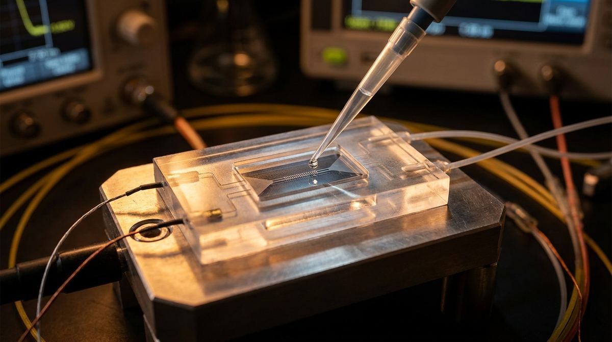
3. Microfluidic Manifold: A PDMS (Polydimethylsiloxane) or glass microfluidic cell to deliver the liquid sample directly over the nanogap.
4. Electrochemical Workstation: A potentiostat with Electrochemical Impedance Spectroscopy (EIS) capabilities, capable of sweeping frequencies from at least 1 Hz to 100 kHz.
5. Reference and Counter Electrodes: Standard micro-electrodes (such as Ag/AgCl) to complete the electrochemical circuit within the microfluidic channel.
6. Buffer Solutions: A series of standard buffer solutions spanning a pH range of 4.0 to 10.0 for calibration.
Prototype Construction Steps
Building a functional nanogap sensor requires precision in both the fabrication of the gap and the integration of the fluidics.
1. Graphene Preparation: Ensure your CVD graphene is clean and well-adhered to the SiO2 substrate. Any large-scale contamination prior to breakdown may lead to unpredictable results.
2. Controlled Electrical Breakdown: This is the most critical step. Place the graphene substrate in an inert atmosphere (Nitrogen or Argon). Apply a controlled DC voltage across the graphene sheet. You are looking for a sudden jump in resistance, which indicates that a nanogap has been formed by electrical breakdown.
3. Microfluidic Integration: Bond the PDMS microfluidic layer to the substrate containing the nanogaps. The channel height should be optimized to ensure the liquid makes consistent contact with the graphene edges. We assume a channel height of 50 to 100 micrometers for initial testing.
4. Electrode Placement: Position your reference and counter electrodes within the microfluidic channel. These must be positioned so that the electric field lines pass through the nanogap area.
5. Connection: Wire the graphene electrodes (source and drain) to the potentiostat to allow for impedance measurements.
Testing and Characterization Protocol
Once the prototype is assembled, follow this testing plan to validate the sensor's sensitivity.
1. Baseline Impedance Measurement: Before introducing the sample, perform an EIS sweep in a neutral buffer (pH 7.0). Use a frequency range of 1 Hz to 100 kHz. This establishes your baseline Warburg impedance.
2. pH Titration Test: Gradually introduce buffer solutions with varying pH levels (e.g., 4.0, 5.0, 6.0, 7.0, 8.0, 9.0, 10.0). At each step, allow the system to stabilize and perform a full EIS sweep.
3. Frequency Response Analysis: Observe how the impedance magnitude and phase angle change as a function of frequency for each pH level. You should see a distinct signature in the low-frequency regime where diffusion-limited processes dominate.
4. Stability Test: Repeat the pH measurements over several hours to ensure the nanogap remains stable and the graphene edges do not undergo significant degradation or irreversible oxidation.
Modeling the Electrochemical Response
To turn raw impedance data into a sensor reading, you must use an equivalent-circuit model. The research suggests that the response is consistent with a model containing a resistor and a capacitor in parallel, combined with a Warburg element.
The Warburg element (W) accounts for the diffusion of ions into the nanogap. By fitting your EIS data to this circuit model, you can extract the effective nanogap length scale. This length scale is a critical parameter; it tells you how much the confinement of the ions is affecting the signal. A smaller, more consistent length scale generally translates to higher sensitivity.
The relationship between the measured impedance and the pH can then be modeled using a calibration curve. As the pH changes, the Warburg impedance shifts in a predictable manner, allowing you to convert an impedance value directly into a pH reading.
Engineering Risks and Mitigation
Working with nanogaps and electrochemical processes involves several technical risks.
1. Gap Unpredictability: Electrical breakdown is a stochastic process. Not every breakdown will result in a usable nanogap. Mitigation: Perform multiple breakdown attempts on different areas of the same chip to increase the probability of success.
2. Edge Degradation: The high electric fields and electrochemical reactions at the graphene edges can cause the edges to erode over time. Mitigation: Limit the voltage applied during testing and use low-concentration electrolytes to minimize aggressive chemical reactions.
3. Contamination Interference: While the research notes that a thin contamination layer is necessary for the electrochemical response, uncontrolled contamination can lead to noise. Mitigation: Use highly purified buffers and controlled environments to ensure that the only conductive film present is the one formed during the initial exposure.
4. Microfluidic Leaks: At the nanoscale, even a tiny leak can ruin the electrochemical signal. Mitigation: Use high-quality plasma bonding for the PDMS-to-substrate interface.
Source Basis and Technical Assumptions
This guide is based on the research findings of McKee et al. (2026) regarding the electrochemical impedance spectroscopy of graphene nanogaps.
The following points are engineering assumptions for the purpose of this practical guide:
- The specific voltage required for electrical breakdown is not provided in the source and is assumed to be in the 1-10V range depending on the substrate.
- The microfluidic channel dimensions (50-100 micrometers) are assumed for practical prototyping.
- The use of Ag/AgCl electrodes is assumed as a standard laboratory practice for electrochemical setups.
- The frequency range (1 Hz to 100 kHz) is a standard starting point for EIS in aqueous solutions.