The Challenge of Nanoscale Strain Monitoring
In the development of flexible electronics, wearable sensors, and micro-electromechanical systems (MEMS), monitoring the mechanical deformation of thin-film materials is critical. Traditional strain gauges, which rely on resistive changes or capacitive shifts, often lack the precision required at the atomic scale and can interfere with the very mechanical properties they are meant to measure. When working with two-dimensional (2D) materials like graphene, the strain is not just a mechanical metric but a fundamental driver of electronic behavior.
As graphene is stretched or twisted, its electronic band structure undergoes significant changes. This research-driven approach moves away from measuring physical displacement and instead focuses on measuring the electronic response. By using ultrafast spectroscopy, we can observe how the electrons react to lattice deformation, providing a direct, non-destructive method to reconstruct the full strain tensor—meaning we can determine both the magnitude and the exact direction of the strain.
The Principle: Electronic Fingerprinting via Van Hove Singularities
The core concept relies on the fact that graphene possesses specific energy states known as van Hove singularities. These are points in the material's density of states where the electronic density is exceptionally high. When the graphene lattice is deformed (strained), these singularities shift in energy and, more importantly, can split into multiple peaks.
According to recent research, these shifts and splittings create a unique spectral signature, often described as a fishbone structure in transient absorption spectroscopy (ATAS). By analyzing these spectral fingerprints, an engineer can mathematically map the observed light absorption back to the specific strain tensor applied to the graphene. This allows for the reconstruction of the lattice deformation with unprecedented speed and accuracy.
Prototype Architecture: The Spectroscopic Strain Sensor
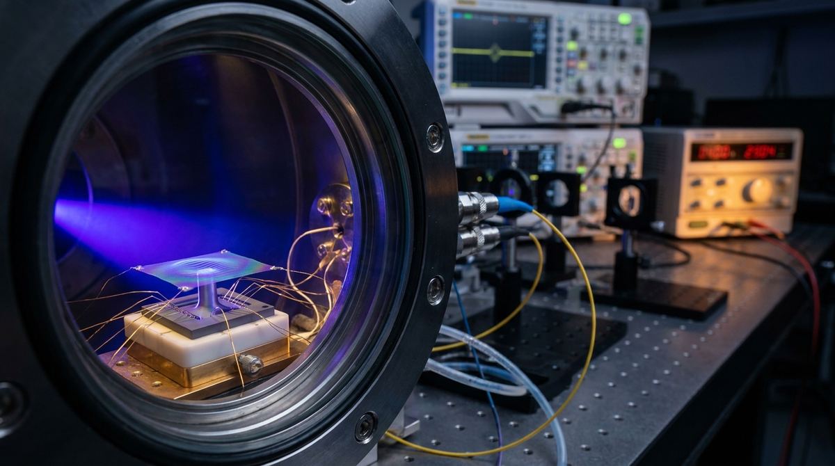
To test this concept, a high-end R&D prototype must be constructed. This is not a desktop maker project; it is an advanced laboratory setup designed for a startup or a materials science lab specializing in quantum metrology.
The system consists of three primary modules:
1. The Sample Stage: A flexible substrate (such as polyimide) mounted on a high-precision piezoelectric actuator. This allows for controlled, incremental strain application.
2. The Excitation Source: An ultrafast laser system capable of producing transient absorption signals. While the research utilizes attosecond pulses, a functional engineering prototype for testing can begin with femtosecond-scale pulses to observe the initial electronic shifts.
3. The Detection System: A high-resolution spectrometer coupled with a fast photodetector to capture the transient absorption spectra.
Required Materials and Equipment
The following list outlines the necessary components for an initial experimental setup.
Substrate: Polyimide (Kapton) film, thickness 25 to 125 micrometers. This provides a stable, flexible base for graphene transfer.
Graphene: High-quality, large-area CVD-grown graphene. The quality of the graphene is paramount; defects will introduce noise into the spectral fingerprints.
Actuation: A piezoelectric stage (e.g., Physik Instrumente) capable of sub-nanometer resolution to ensure the strain applied is controlled and measurable.
Laser System: A Ti:Sapphire femtosecond laser system is a recommended starting point for a lab-scale prototype. For true attosecond reconstruction as described in the research, an X-ray Free Electron Laser (XFEL) or a high-harmonic generation (HHG) source would be required.
Detection: A broadband spectroscopic setup capable of measuring transient absorption in the ultraviolet to visible range.
Assembly and Implementation Steps
1. Substrate Preparation: Clean the polyimide substrate using standard plasma cleaning to ensure maximum adhesion for the graphene layer.
2. Graphene Transfer: Use a standard PMMA-assisted wet transfer method to deposit the CVD graphene onto the polyimide. Ensure the graphene is continuous and free of significant wrinkles or polymer residue.
3. Mechanical Integration: Mount the polyimide substrate onto the piezoelectric actuator. The actuator should be configured to apply uniaxial or biaxial tension depending on the desired strain tensor complexity.
4. Optical Alignment: Align the pump-probe laser setup. The pump pulse excites the graphene, and the probe pulse measures the change in absorption. The probe must be focused precisely on the area of the graphene subjected to the mechanical load.
5. Calibration of the Baseline: Measure the transient absorption spectrum of the graphene at zero strain. This provides the reference state for the van Hove singularities.
6. Incremental Loading: Apply strain in small, controlled increments (e.g., 0.01%, 0.05%, 0.1%). At each step, capture the transient absorption spectrum.
Testing and Calibration Protocol
The goal of the test is to establish a mathematical correlation between the spectral shifts and the applied strain.
1. Magnitude Mapping: Observe the shift in the energy position of the van Hove singularity peaks. As strain increases, the peak position should shift predictably. Plot the peak shift (in eV) against the applied strain (in percent).
2. Orientation Mapping: Apply shear strain by tilting the substrate or using a specialized biaxial stage. Observe the splitting of the peaks. The degree of splitting and the relative intensity of the split peaks will encode the direction of the strain.
3. Tensor Reconstruction: Use the analytical modeling suggested in the research to convert the observed spectral data into a strain tensor. This involves comparing the experimental data against density-matrix simulations to ensure the reconstructed lattice deformation matches the physical reality.
Engineering Risks and Mitigation
Complexity of the Pulse: The research emphasizes attosecond-scale pulses. Using femtosecond pulses may only provide a partial view of the electronic response. If the signal is too weak, the engineer must upgrade to a higher-frequency harmonic generation source.
Signal-to-Noise Ratio: The electronic fingerprints are subtle. Substrate vibrations or thermal fluctuations can mask the spectral shifts. Mitigation requires an ultra-stable optical table and vacuum-based measurement environments to prevent air-induced refractive index changes.
Substrate Interference: The polyimide substrate will also undergo strain. It is vital to distinguish between the strain in the graphene and the strain in the substrate. This is mitigated by using very thin graphene layers and ensuring the laser probe is tuned specifically to the graphene's electronic transitions, avoiding the substrate's absorption bands.
Thermal Loading: High-intensity laser pulses can cause local heating, which induces thermal strain. This can be mistaken for mechanical strain. Mitigation involves using low-repetition-rate lasers or extremely short pulses to minimize the cumulative thermal load on the sample.
Source Basis
This guide is based on the research findings of Li et al. (2026) regarding the attosecond reconstruction of strain tensors via electronic fingerprints. The implementation steps and hardware recommendations are engineering assumptions intended to translate the theoretical spectroscopic paradigm into a functional laboratory prototype.