The Shift to Electronic Hydrodynamics
In traditional semiconductor engineering, we treat electrons as a gas of independent particles moving through a lattice. However, in ultra-high mobility materials like bilayer graphene, a different regime emerges: the hydrodynamic regime. In this state, electron-electron scattering becomes the dominant interaction, causing the electron population to behave less like a gas and more like a viscous fluid.
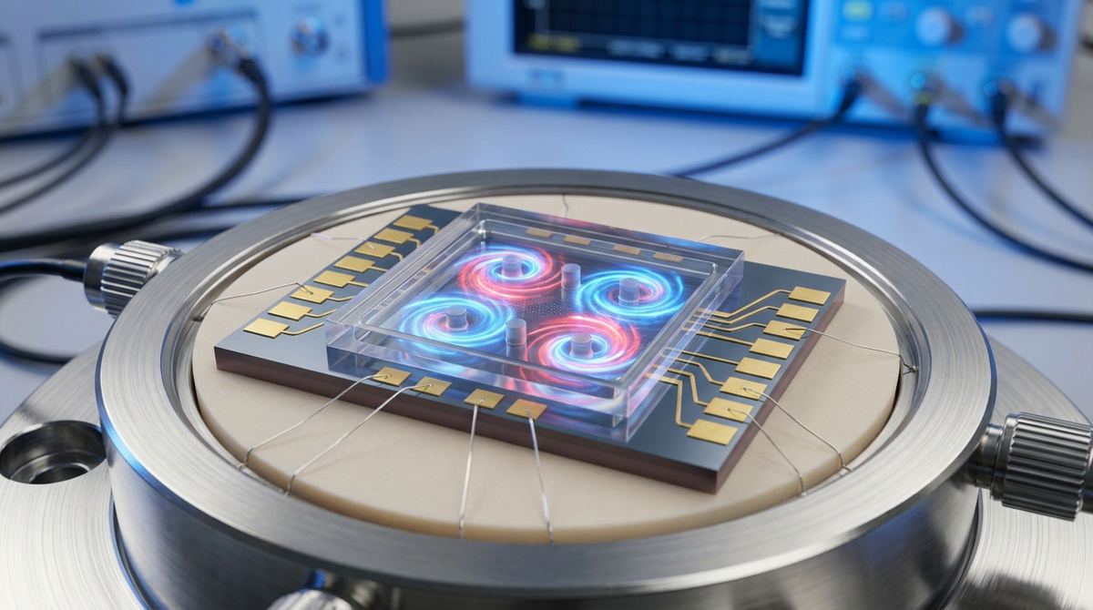
When electrons flow as a fluid, they can exhibit phenomena typically reserved for classical hydraulics, such as vortices and turbulence. Recent research by Panigrahi and Nazaryan (2026) has identified a specific phenomenon called viscochiral transport. This occurs when a spatial gradient in Hall viscosity—driven by Berry curvature—is applied to the fluid. This gradient can selectively amplify or suppress vortices in different parts of a device. For an engineer, this represents a new way to control electron flow: not just by blocking it with a barrier, but by using the fluid dynamics of the electrons to route them.
The Application: The Vortex-Based Electronic Router
The primary practical application for this effect is the development of a non-reciprocal electronic router. In standard electronics, a resistor or a transistor acts as a gate that is either on or off. A vortex-based router, however, uses the chiral selection of hydrodynamic vortices to direct the flow of the electron fluid into specific channels based on the direction of the current or the local Berry curvature.
By creating a device where the Hall viscosity varies spatially, we can force the electron fluid to circulate in a clockwise direction in one chamber and a counter-clockwise direction in another. This allows for the creation of "vortex-based logic" or non-reciprocal components that allow current to pass in one direction while suppressing it in the other, without the need for magnetic fields or traditional p-n junctions.
Materials and Hardware Requirements
Building a prototype for viscochiral transport requires extreme precision in material quality. Because the hydrodynamic regime relies on electron-electron scattering dominating over electron-impurity scattering, the sample must be exceptionally clean.
1. Bilayer Graphene: You must use high-mobility bilayer graphene. Single-layer graphene does not possess the necessary Berry curvature properties for this specific effect.
2. Hexagonal Boron Nitride (hBN): This is required for encapsulation. The graphene must be sandwiched between two flakes of hBN to minimize substrate scattering and maintain the hydrodynamic regime.
3. Silicon/SiO2 Substrate: A standard substrate for device fabrication.
4. Electrostatic Gates: You will need a series of patterned gates (likely gold or titanium) to create the spatial gradient in the valley polarization.
5. Electron Beam Lithography (EBL) System: Necessary for defining the fine geometries required for the micro-cavities.
6. Cryogenic Environment: While the paper suggests the regime is accessible, successful observation will likely require temperatures below 10 Kelvin to suppress phonon scattering.
Prototype Fabrication Steps
The following steps outline the assembly of a micro-cavity device designed to test the chiral selection of vortices.
1. Substrate Preparation: Clean a silicon/SiO2 substrate using standard RCA cleaning procedures to ensure no organic contaminants remain.
2. Gate Patterning: Use EBL to pattern a series of split-gates or tapered gates on the substrate. These gates are the most critical component. They must be designed to create a spatial gradient in the carrier density and, more importantly, a gradient in the valley polarization of the bilayer graphene. We assume a tapered gate geometry where the width of the gate electrode changes linearly across the device area.
3. Stack Assembly: Using a dry transfer method (such as a PC/PDMS stamp), pick up a thin flake of hBN, followed by a high-quality bilayer graphene flake, and then a second flake of hBN. The bilayer graphene must be perfectly aligned with the underlying gates.
4. Micro-cavity Etching: To observe vortices, the electron fluid needs a confined geometry. Use Reactive Ion Etching (RIE) to define micro-cavities within the graphene/hBN stack. These cavities should be roughly 5 to 10 micrometers in width to allow for stable vortex formation.
5. Contact Metallization: Deposit gold/titanium contacts using EBL and evaporation. Ensure the contacts are placed at the edges of the micro-cavities to allow for the measurement of non-local transport.
6. Encapsulation: Perform a final encapsulation step to protect the device from atmospheric degradation.
Test Plan and Validation
To verify that the device is operating in the viscochiral regime, you must move beyond simple resistance measurements.
1. Non-Local Resistance Mapping: Apply a current through two leads and measure the voltage at two other leads located far from the classical current path. In the hydrodynamic regime, the non-local voltage will be significantly higher due to the flow of the electron fluid.
2. Phase Diagram Mapping: Systematically vary the gate voltages to change the spatial gradient of the Hall viscosity. According to the Panigrahi-Nazaryan model, you should observe a transition where vortices are amplified in one chamber and suppressed in another.
3. Temperature Sweeps: Measure the device from 4K up to 50K. The effect should diminish as temperature increases and phonon scattering begins to dominate over electron-electron scattering.
4. Current Directionality Test: Apply current in both directions. If the device is successfully acting as a vortex router, the voltage response should be asymmetric due to the chiral selection of the flow patterns.
Engineering Assumptions and Risks
It is important to distinguish between the theoretical predictions of the research and the practical implementation.
Assumption 1: The paper predicts the effect is generic to recirculating flows and insensitive to geometry. However, for a practical prototype, we assume that a micro-cavity geometry is necessary to stabilize the vortices for measurement.
Assumption 2: The paper states the regime is accessible in valley-polarized bilayer graphene. We assume that a spatial gradient in the Berry curvature can be effectively achieved through electrostatic gating, though the exact voltage ranges required to reach this regime are not specified. We suggest starting with gate voltages in the range of -5V to -20V to tune the carrier density.
Assumption 3: We assume that the hydrodynamic regime can be maintained at temperatures accessible by standard dilution refrigerators (below 1K) or even liquid Helium temperatures (4K).
Risks:
The primary risk is sample disorder. If the graphene has too many defects or the hBN interface is rough, the electron fluid will behave like a gas, and the viscochiral effect will be washed out by impurity scattering.
Another risk is the difficulty of measurement. Detecting a vortex directly is extremely difficult; we are relying on indirect transport measurements (non-local resistance) to infer the presence of the vortex. If the signal-to-noise ratio is too low, the chiral selection may be impossible to distinguish from standard non-reciprocal effects caused by geometry.