
Unlocking Superconductivity in Twisted Graphene: A Gutzwiller Study Explained
Explore how theoretical physics unlocks the secrets of strongly correlated superconductivity in twisted bilayer graphene, a key step toward future quantum...
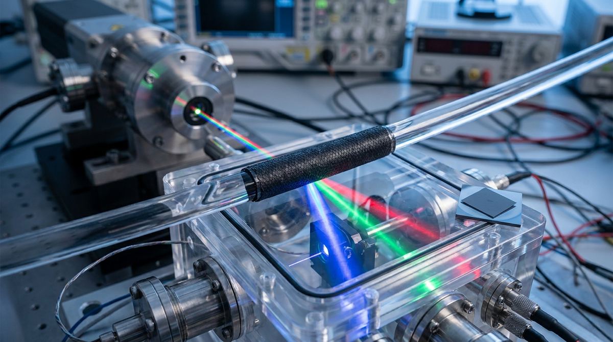
In traditional photonics, we manipulate light by changing the physical shape or the refractive index of a material through spatial means. We use lenses to bend light or gratings to diffract it. However, a new frontier in engineering is moving from spatial modulation to temporal modulation. Instead of changing where the light goes, we change the material properties of the medium while the light is passing through it. This is known as time-varying photonics.
The research by Tavakol and Cai (2026) highlights a significant breakthrough in modeling these systems using a full-wave harmonic-balance framework. For an engineer or a startup, the most practical application of this theory is the creation of a graphene-based frequency converter. By modulating the conductivity of a graphene layer at extremely high speeds, we can force incident light to shift its frequency, creating new sidebands or "Floquet harmonics." This has massive implications for optical signal processing, high-speed telecommunications, and the generation of optical frequency combs.
This guide focuses on building a prototype of a parametrically pumped rolled graphene cylinder, a specific geometry validated in the research, to demonstrate frequency conversion.
The primary difficulty in building a time-varying device is that the material response is no longer a single number. In a standard material, the relationship between the electric field and the current is constant. In a time-varying material, the material response changes during the interaction. This creates new frequencies.
If you shine a laser of frequency f0 into a material whose conductivity is being modulated at frequency fm, the output will contain frequencies like f0 + fm, f0 - fm, 2fm - f0, and so on. The challenge is that as you increase the modulation speed, the material's dispersive nature (how it responds to different frequencies) becomes critical. You cannot simply assume the graphene behaves the same at the original frequency and the new sideband frequencies. This is why the harmonic-balance framework mentioned in the source is essential for design; it accounts for how each harmonic experiences a different material response while remaining coupled to the others.
To build a laboratory-scale prototype of a rolled graphene cylinder, you will need the following:
1. Graphene: High-quality, large-area CVD (Chemical Vapor Deposition) grown graphene is required. The mobility of the charge carriers directly impacts the efficiency of the frequency conversion.
2. Substrate: A flexible, low-loss dielectric such as Quartz or a thin layer of Polyimide. This will serve as the base for the cylinder.
3. Electrodes: Gold or Palladium for making electrical contacts to the graphene to allow for gate voltage modulation.
4. Pump Laser: A high-power, continuous-wave (CW) or pulsed laser to act as the parametric pump. This laser provides the energy needed to modulate the graphene's carrier density.
5. Probe Laser: A tunable laser source to provide the input signal for frequency conversion.
6. Detection System: A high-resolution optical spectrum analyzer (OSA) or a spectrometer capable of resolving sidebands in the THz or optical range.
7. Signal Generator: A high-frequency microwave or THz source to drive the modulation if using electrical gating, though optical pumping is often more efficient for high-speed applications.
The following steps outline the construction of a rolled graphene cylinder. Note that the exact dimensions are engineering assumptions based on typical micro-scale photonic components.
1. Substrate Preparation: Clean a thin quartz substrate using standard RCA cleaning procedures to ensure no organic contaminants interfere with the graphene transfer.
2. Graphene Depstrate and Transfer: Use a standard PMMA-assisted transfer method to deposit the CVD graphene onto the quartz substrate. Ensure the graphene is continuous and free of excessive wrinkles or cracks.
3. Electrode Patterning: Use photolithography to define gold electrodes on the substrate. These electrodes will be used to apply a gate voltage to the graphene, which is one method of modulating its conductivity.
4. Cylinder Rolling: This is the most delicate step. The substrate must be mechanically rolled into a cylinder shape. For a prototype, aim for a cylinder diameter of approximately 100 to 500 micrometers. The graphene must remain tightly adhered to the substrate throughout the bending process. This can be achieved using a specialized mandrel or a micro-mechanical rolling stage.
5. Electrical Connection: Once the cylinder is formed, use a probe station to establish electrical contact with the gold electrodes.
6. Optical Alignment: Mount the cylinder in an optical breadboard. The probe laser should be aligned to enter the cylinder, and the pump laser should be aligned to interact with the graphene layer, either through direct absorption or via a high-intensity field.
The goal of the test is to observe the generation of Floquet harmonics (sidebands).
1. Baseline Measurement: Shine the probe laser through the static graphene cylinder and record the spectrum using the OSA. This establishes the input frequency f0.
2. Parametric Pumping: Activate the pump laser. The pump laser should be tuned to a frequency that modulates the graphene's conductivity.
3. Sideband Detection: Monitor the spectrum for new peaks at f0 +/- fm. The efficiency of the device is measured by the ratio of the power in the sidebands to the power in the original probe signal.
4. Angular Dependency: Since the research mentions "dynamic wavefront control," rotate the cylinder or change the angle of incidence of the probe laser. Observe how the spatial diffraction orders of the sidebands change. This confirms the device is performing wavefront control rather than just simple frequency shifting.
Because the research is a theoretical framework, we must make several assumptions for a physical build:
1. Modulation Frequency: The research discusses time-varying structures, but does not specify the exact modulation frequency for the cylinder. For an optical application, we assume a modulation frequency in the GHz to THz range. If using electrical gating, you will need high-speed RF equipment.
2. Gate Voltage: We assume a gate voltage range of 0 to 10V to tune the graphene from the charge neutrality point to a highly doped state.
3. Cylinder Dimensions: We assume a cylinder length of 1 to 5 mm and a diameter of 100-500 micrometers.
4. Temperature: The experiment should be conducted in a temperature-controlled environment, as graphene's mobility is highly sensitive to thermal fluctuations.
1. Thermal Damage: The pump laser required for parametric pumping can be quite intense. Excessive heat can damage the graphene or the substrate.
Mitigation: Use a pulsed pump laser with a low duty cycle to minimize heat accumulation, or implement active cooling if using a CW laser.
2. Mechanical Stress: Rolling the substrate can cause the graphene to crack or delaminate, especially if the substrate is too rigid.
Mitigation: Use very thin substrates (less than 50 micrometers) and perform the rolling process slowly using a precision motorized stage.
3. Signal-to-Noise Ratio: The sidebands generated by time-varying modulation are often much weaker than the primary signal.
Mitigation: Use high-sensitivity detectors and ensure the probe laser is highly monochromatic to prevent overlapping with the sidebands.
4. Impedance Mismatch: At high modulation frequencies, the electrical connections to the graphene may act as antennas or create reflections.
Mitigation: Use professional-grade RF connectors and design the electrode geometry to minimize parasitic capacitance.
Serious about B2B integration? Test our premium Pulsed Electrical Resistive Carbon Heating turbostratic graphene in your lab. 100g sample packs available now.
Explore More
Explore how theoretical physics unlocks the secrets of strongly correlated superconductivity in twisted bilayer graphene, a key step toward future quantum...

Explore how the intrinsic band geometry of 2D materials can induce valley polarization of chiral excitons, a key step toward next-gen valleytronics.

Explore a new class of pressure sensors using graphene to detect pressure-enhanced polarization in ferroelectric boron nitride, a novel slidetronic effect.