
A New Era of Graphene Engineering: Pre-Designing Twist Angles on Demand
Researchers have developed a breakthrough method for growing twisted bilayer graphene with pre-designed angles, a key step toward manufacturable quantum...
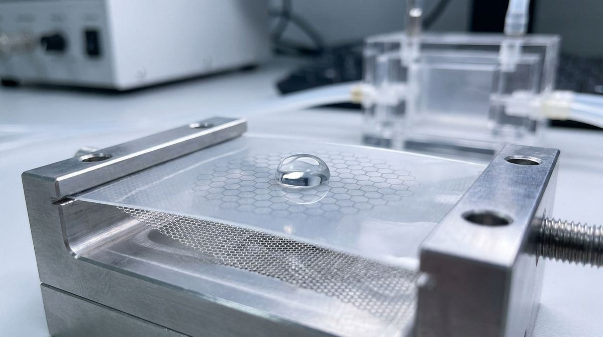
The world of membrane science is dominated by a fundamental trade-off: permeability versus selectivity. For applications like water desalination and purification, you want a membrane that allows water to pass through quickly (high permeability) while blocking salts and contaminants (high selectivity). The most straightforward way to increase water flux is to make the selective layer of the membrane thinner. Unfortunately, an ultra-thin polymer film is mechanically fragile and would rupture under the high pressures used in filtration processes.
Engineers have long solved this by casting the thin selective polymer layer onto a thick, porous, and robust support. But what if the support layer itself could be atomically thin yet stronger than steel? This is where graphene enters the picture. A recent computational study provides a fascinating insight that we can translate into a practical, high-performance filtration prototype. This guide will walk you through how to build a composite membrane using a porous graphene sheet as a mechanical support for an ultra-thin polymer filtration layer, a concept directly inspired by a molecular dynamics simulation.
Our project is based on the findings in a 2026 paper by Jannik Mehlis and Matthias Wessling titled, "Decoupling support-dependent transport profiles from molecular water motion." It's important to understand that this paper is not an experimental guide; it's a computational study. The researchers used non-equilibrium molecular dynamics (NEMD) to simulate water transport through a polymer membrane, specifically crosslinked poly(ethylene glycol) diacrylate (PEGDA).
To stabilize their virtual membrane in the simulation, they tested several mechanical restraints, one of which was a rigid graphene lattice. Their key discovery was that while the type of support dramatically changed the simulated pressure and concentration profiles, the actual molecular behavior of the water—its diffusion and movement within the polymer—remained almost identical.
This is a profound insight for the practical engineer. It suggests that a graphene support can act as a purely mechanical scaffold. It provides the necessary strength to hold an ultra-thin polymer layer without interfering with or altering the intrinsic water transport mechanism of that polymer. We can therefore leverage graphene's incredible strength to make the polymer layer thinner than ever before, drastically increasing water flux without sacrificing the polymer's inherent selectivity. This guide translates their virtual graphene support into a physical, testable prototype.
You will construct a composite water filtration membrane. This prototype will consist of two primary components:
1. A Nanoporous Graphene Support Layer: A single layer of CVD graphene, made permeable by introducing a high density of nanopores. This layer provides the mechanical strength.
2. An Ultra-Thin Selective Polymer Layer: A thin film (targeting less than 100 nm) of crosslinked PEGDA hydrogel, formed directly on top of the graphene support. This layer performs the actual separation.
The final assembly will be a membrane capable of withstanding hydraulic pressure while exhibiting significantly higher water flux than conventional polymer membranes of similar selectivity. This project is ideal for a small lab or startup exploring next-generation water and environmental applications.
This build requires materials and equipment common in materials science and chemistry labs.
Materials:
Graphene: Chemical Vapor Deposition (CVD) graphene on copper foil (at least 1x1 cm squares).
Polymer Precursors: Poly(ethylene glycol) diacrylate (PEGDA, average Mn 575-700), and a photoinitiator like 2,2-Dimethoxy-2-phenylacetophenone (DMPA).
Solvents and Reagents: Deionized (DI) water, isopropanol, acetone, PMMA (Polymethyl methacrylate), copper etchant (e.g., ammonium persulfate or ferric chloride).
Substrates: A perforated support to hold the final membrane. Silicon nitride (SiN) TEM grids are excellent for small-scale tests. For larger tests, a silicon wafer with a window etched through it or a custom 3D-printed filter holder can be used.
Equipment:
Spin Coater: For applying thin, uniform polymer films.
UV Curing System: A UV lamp with a primary emission around 365 nm.
Plasma System: A reactive-ion etcher (RIE) or plasma cleaner with oxygen gas supply for creating pores in the graphene.
Filtration Test Rig: A dead-end or cross-flow filtration cell capable of applying pressure and measuring permeate flow.
Conductivity Meter: To measure salt concentration in feed and permeate water.
Microscopy: Access to a Scanning Electron Microscope (SEM) and/or Atomic Force Microscope (AFM) for characterization is highly recommended.
Standard Lab Equipment: Beakers, hot plate, tweezers, fume hood.
This process involves delicate transfer and fabrication steps. Work carefully in a clean environment to minimize defects.
1. Prepare the Graphene Support
The first major phase is to transfer the graphene from its copper growth substrate to your final perforated support and then make it porous.
Spin-coat a layer of PMMA onto the graphene/copper foil. This PMMA layer will serve as a temporary handle.
Bake the PMMA-coated foil to remove solvent (e.g., 180°C for 2 minutes).
Float the foil on a bath of copper etchant to dissolve away the copper. This will leave you with a floating PMMA/graphene film.
Carefully transfer the film through several DI water baths to rinse away etchant residue.
Scoop the floating film out of the water using your target perforated substrate (e.g., a SiN grid). Let it dry completely.
Remove the PMMA handle by dissolving it in acetone, leaving the single-layer graphene suspended over the perforations in your substrate.
2. Introduce Nanopores
An intact graphene sheet is impermeable. You must create pores for water to pass through. This is a critical step requiring careful calibration.
Place your graphene-on-substrate into a plasma system.
Use a gentle oxygen plasma treatment to etch nanopores into the graphene lattice.
Engineering Assumption: The source paper provides no parameters for this. As a starting point, try a low power (10-30 W) and very short exposure times (5-20 seconds). The goal is to create a high density of small pores (target 5-20 nm diameter) without completely destroying the sheet. You will need to experiment with power and time to find the optimal conditions for your specific system.
3. Apply the Selective Polymer Layer
Now you will form the thin PEGDA hydrogel layer on top of your porous graphene support.
Prepare the precursor solution. Engineering Assumption: Based on typical hydrogel synthesis, a good starting point is a solution of 20 wt% PEGDA and 1 wt% DMPA photoinitiator dissolved in DI water. Mix thoroughly.
Place your porous graphene support in the spin coater.
Dispense a few drops of the precursor solution onto the center of the graphene.
Spin-coat to create a thin, uniform liquid film. Engineering Assumption: To achieve a sub-100 nm film, start with a spin speed of 3000-4000 rpm for 60 seconds. You will need to calibrate this for your specific solution viscosity and desired thickness.
Immediately transfer the coated membrane to a UV curing system. Expose it to 365 nm UV light to crosslink the PEGDA and form a stable, solid hydrogel film. Engineering Assumption: An exposure time of 60-180 seconds is a typical range, but this depends on your lamp intensity and initiator concentration.
Your composite membrane is now complete and ready for testing. This combination of a strong support and a thin selective layer is a hallmark of advanced reinforced polymer composites.
A rigorous test plan is essential to validate your prototype's performance.
1. Structural Verification
Before filtration testing, confirm that you built what you intended to build.
SEM Imaging: Use an SEM to visualize the membrane surface. You should be able to see the polymer coating. If possible, use high magnification to verify the presence of pores in the underlying graphene (this can be difficult if the polymer coating is conformal).
AFM Imaging: Use an AFM to measure the thickness of your PEGDA layer and characterize its surface roughness. This confirms you have achieved an "ultra-thin" layer.
2. Performance Evaluation
Mount the membrane in your filtration cell. Be careful during assembly to ensure a good seal and avoid damaging the membrane.
Water Permeability (Flux): Start with pure DI water. Apply a constant pressure (e.g., 2 bar) and measure the volume of water that passes through the membrane over a set period. Calculate the flux, typically expressed in Liters per square meter per hour (L m⁻² h⁻¹). Compare this value to commercial reverse osmosis or nanofiltration membranes; you are hoping for a significantly higher value.
Solute Rejection (Selectivity): Prepare a feed solution with a known salt concentration (e.g., 1000 ppm NaCl in DI water). Measure the electrical conductivity of this feed solution. Run the filtration test and collect the permeate (the filtered water). Measure the conductivity of the permeate. The rejection percentage can be calculated as: Rejection % = (1 - (Conductivity_permeate / Conductivity_feed)) 100. A high rejection rate (e.g., >95%) combined with high flux is the goal.
Remember the inspiration for this project: the Mehlis & Wessling simulation. Their work gives us confidence that this physical design is sound. The simulation showed that the fundamental mechanism of water transport—a stochastic, diffusion-dominated process—is a property of the PEGDA polymer itself. The graphene support, in their model, acted as an ideal mechanical stabilizer.
Our prototype is a direct attempt to realize this ideal scenario. By using real graphene, we provide the strength needed to make the PEGDA layer exceptionally thin. The research suggests this support should not interfere with the polymer's filtration job. Therefore, any increase in flux we measure should be a direct result of reducing the transport path length (the membrane thickness), demonstrating a successful decoupling of mechanical and transport properties. This is a powerful example of how computational materials science can guide practical graphene applications.
This is an advanced project with several challenges.
Polymer-Graphene Adhesion: The PEGDA hydrogel may not adhere well to the pristine graphene surface, leading to delamination under pressure. If this occurs, you may need to functionalize the graphene surface (e.g., with a brief oxygen plasma treatment before coating) to introduce chemical groups that improve bonding.
Pore Infiltration: The low-viscosity polymer precursor might wick into and clog the nanopores in the graphene instead of forming a clean layer on top. If SEM analysis shows this, try increasing the viscosity of your precursor solution or exploring alternative deposition methods like interfacial polymerization.
Scalability: This guide describes a lab-scale prototype. Scaling up the production of large-area, defect-free porous graphene is a significant engineering hurdle. The field of scalable graphene production is advancing rapidly, but this remains a key challenge for commercialization. For larger supports, materials like turbostratic graphene flakes could potentially be processed into porous support films, offering an alternative to single-crystal CVD graphene.
Success with this prototype opens the door to numerous possibilities. You can experiment with different polymer chemistries for targeted separations, optimize the graphene pore size and density, and explore methods for creating larger, more robust membranes. This project sits at the intersection of nanomaterials, polymer science, and process engineering, offering a tangible path toward next-generation separation technologies.
Serious about B2B integration? Test our premium Pulsed Electrical Resistive Carbon Heating turbostratic graphene in your lab. 100g sample packs available now.
Explore More
Researchers have developed a breakthrough method for growing twisted bilayer graphene with pre-designed angles, a key step toward manufacturable quantum...

Learn how deep learning is revolutionizing the structural characterization of twisted bilayer materials, accelerating the development of next-generation...

Learn to build a prototype graphene FET biosensor for sensitive DNA detection. This guide covers materials, fabrication, and testing for point-of-care...