
Unlocking Quasicrystal Physics in 30-Degree Twisted Bilayer Graphene
Research on 30° quasi-periodic twisted bilayer graphene reveals a unique, fractal-like energy structure under magnetic fields, paving the way for novel...
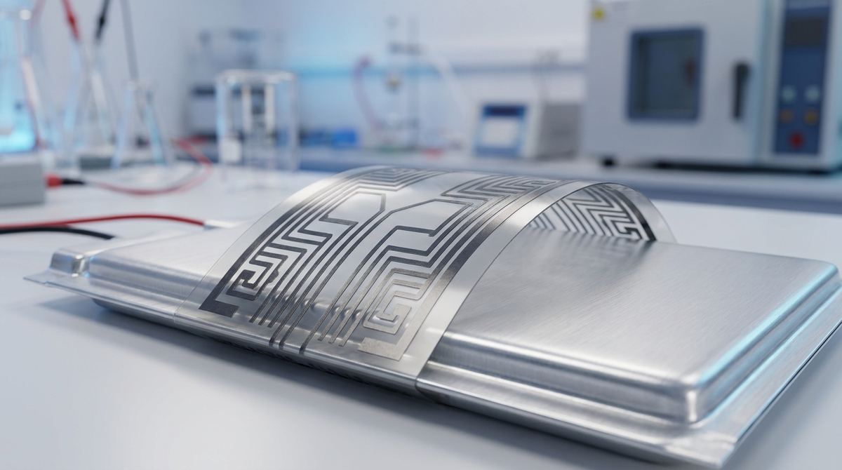
The silent threat lurking within many modern devices, from electric vehicles to the smartphone in your pocket, is battery failure. Lithium-ion batteries, for all their energy density, are susceptible to a catastrophic process called thermal runaway. This can be triggered by internal short circuits, overcharging, or physical damage, often preceded by two key physical indicators: a rapid rise in temperature and subtle mechanical swelling or strain. Monitoring these precursors is the key to preventing disaster.
Existing battery management systems often rely on rigid, single-purpose sensors that fail to capture the full picture. A thermocouple can measure temperature, but it won't detect the dangerous cell deformation that signals internal pressure buildup. Strain gauges can detect swelling but are blind to thermal issues. Furthermore, their rigidity makes them poorly suited for the dynamic, expanding and contracting surface of a battery pouch cell.
This guide outlines a practical approach to fabricating a flexible, multifunctional sensor capable of monitoring both temperature and strain simultaneously. Based on research by Shihao Dang et al. (2026), this project uses a laser direct writing process to create a sensor from a graphene-silver nanoparticle composite. The addition of graphene dramatically enhances the sensor's sensitivity, creating a powerful tool for early-stage battery fault detection. We will walk through the materials, fabrication steps, and testing protocols to create a working prototype for your lab or startup.
The goal is to create a thin, flexible sensor film that can be directly applied to the surface of a lithium-ion battery, specifically a pouch cell. This sensor will have two distinct, electrically isolated components fabricated in a single process:
1. A Strain Sensor: This element will be designed as an interdigitated capacitor or a simple resistive line pattern. Its electrical resistance will change predictably as the battery surface beneath it stretches or deforms, allowing you to quantify cell swelling.
2. A Temperature Sensor: This element will be designed in a serpentine pattern to maximize its length within a small area. Its resistance will change in direct correlation with temperature, providing precise thermal monitoring.
Both sensors will be patterned onto a single polyimide substrate using a laser to selectively sinter a custom ink made from reduced graphene oxide and silver nanoparticles. The final product will be a robust, lightweight, and highly sensitive monitoring device that provides a more complete picture of battery health than conventional methods.
This project requires specialized materials and equipment common in materials science or electronics prototyping labs.
Materials:
Substrate: Polyimide (PI) film, often known by the brand name Kapton. A thickness of 50-125 micrometers is a good starting point due to its flexibility and high-temperature tolerance.
Precursor Ink Components:
Reduced Graphene Oxide (rGO): While the source paper uses rGO, high-quality turbostratic graphene flakes can be an excellent starting material for creating your own rGO dispersion. You will need a fine powder form.
Silver Nanoparticles (AgNPs): A dispersion of AgNPs with an average particle size of 20-50 nm. These are commercially available from various chemical suppliers.
Solvent and Binders: A high-boiling-point solvent like terpineol or ethylene glycol is needed to create a paste-like ink. A binder such as ethyl cellulose may be required to improve viscosity and adhesion.
Conductive Epoxy or Paste: For attaching electrical leads to the sensor contact pads.
Test Battery: A lithium-ion pouch cell is ideal for this application, as its swelling is visually and mechanically apparent. Use a small, low-capacity cell for initial safety testing.
Equipment:
Laser Direct Writing (LDW) System: This is the core piece of equipment. A system with a controllable UV (355 nm) or fiber laser (1064 nm) is ideal. Power, scan speed, and spot size must be precisely adjustable. If a dedicated LDW system is unavailable, a well-calibrated laser cutter or engraver with fine control might be adapted for this purpose, though results will vary. Explore options for industrial synthesis equipment if scaling up.
Ink Preparation Tools: An ultrasonic bath or probe sonicator for dispersing the nanoparticles and graphene, and a planetary mixer or magnetic stirrer for ensuring a homogenous ink.
Film Coating Tool: A spin coater or a doctor blade applicator to create a uniform layer of the precursor ink on the polyimide substrate.
Digital Multimeter or Source Measure Unit (SMU): For precise resistance measurements. An SMU is preferred for its ability to source voltage and measure current accurately.
Testing Apparatus:
A programmable hot plate or small environmental chamber for temperature sensor calibration.
A commercial thermocouple for reference temperature measurements.
A setup for applying controlled strain, which can range from a simple cantilever beam with known deflection to a professional tensile tester.
A battery cycler or programmable power supply to charge and discharge the test battery.
This process requires precision and patience, especially during ink formulation and laser parameter calibration.
1. Prepare the Precursor Ink
This is a critical step, as the ink's properties will determine the final sensor's performance. The source abstract does not specify ratios, so this is an engineering assumption.
Start with a 1:1 weight ratio of rGO to AgNPs. This ratio can be adjusted later to optimize for either temperature or strain sensitivity.
Disperse the rGO and AgNPs in your chosen solvent (e.g., terpineol). Aim for a total solids content of around 20-40% by weight.
Use a sonicator to break up agglomerates and create a stable, uniform dispersion. This may take 30-60 minutes.
If needed, add a small amount of ethyl cellulose binder (e.g., 1-2% of the total weight) and mix thoroughly to achieve a honey-like viscosity suitable for coating.
2. Design the Sensor Pattern
Use any CAD or vector graphics software to design your sensor layout. The design should include two separate circuits on the same film.
Temperature Sensor: A long, thin, serpentine (snake-like) pattern. This maximizes the resistive path length in a compact area, increasing its sensitivity to temperature changes.
Strain Sensor: A simple, straight line or an interdigitated pattern. The source paper's results suggest that the graphene-silver composite itself is highly sensitive, so a simple line may suffice for initial tests.
Contact Pads: Design larger square pads at the end of each sensor trace for connecting wires. Ensure adequate spacing between the two sensor circuits to minimize crosstalk.
3. Coat the Substrate
Thoroughly clean the polyimide film with isopropyl alcohol to remove any contaminants.
Apply the precursor ink onto the film. For a uniform layer, use a spin coater (e.g., 30 seconds at 1000 RPM) or a doctor blade with a fixed gap (e.g., 100 micrometers).
Gently heat the coated film on a hotplate at a low temperature (e.g., 60-80°C) for 10-15 minutes to evaporate some of the solvent and stabilize the ink layer. This is called a soft bake.
4. Laser Direct Writing
This step transforms the non-conductive ink into the final conductive sensor pattern. The laser's energy selectively sinters the AgNPs and reduces any remaining oxygen groups on the rGO. Laser parameters are highly system-dependent and require calibration.
Secure the coated substrate to the LDW stage.
Load your sensor pattern file into the control software.
Begin with low power and high scan speed to avoid damaging the substrate. A good starting point for a UV laser might be 0.5 W power with a scan speed of 100 mm/s.
Perform a series of test patterns, systematically adjusting power and speed. Measure the resistance of the resulting lines with a multimeter. You are looking for the lowest resistance without burning through the polyimide film.
Once optimized, run the laser process for your full sensor design. The laser will trace the pattern, leaving behind sintered, conductive paths.
5. Post-Processing
After laser writing, the unsintered ink must be removed. Gently wash the film in a solvent bath (e.g., ethanol or acetone) to dissolve and rinse away the excess material, leaving only your sensor patterns on the substrate.
Using a small amount of conductive epoxy, carefully attach thin, flexible wires to the contact pads of each sensor. Cure the epoxy according to the manufacturer's instructions.
A systematic testing plan is essential to characterize your sensor and validate its performance against the research paper's claims.
1. Temperature Sensor Calibration
Connect the temperature sensor leads to your multimeter or SMU set to measure resistance.
Place the sensor, along with a reference thermocouple, onto a programmable hot plate or into an environmental chamber.
Slowly ramp the temperature from room temperature (e.g., 25°C) up to a safe limit for a battery (e.g., 80°C) in 5°C increments.
At each step, allow the temperature to stabilize and record the sensor's resistance and the reference thermocouple's reading.
Plot resistance versus temperature. The relationship should be nearly linear. Calculate the Temperature Coefficient of Resistance (TCR), which is a key performance metric.
2. Strain Sensor Calibration
Secure one end of the sensor film and attach the other to a mechanism that can apply measurable strain (e.g., a linear actuator or a bending rig).
Connect the strain sensor leads to your SMU.
Apply small, incremental amounts of strain (e.g., 0.05%, 0.1%, 0.2%) and record the change in resistance.
Calculate the Gauge Factor (GF), defined as the fractional change in resistance divided by the fractional change in length (strain). The source paper achieved a GF of over 20, a significant improvement enabled by the graphene.
Test for durability by repeatedly bending or stretching the sensor for at least 1000-2000 cycles and checking for drift in the baseline resistance.
3. Integrated Battery Monitoring Test
This is the ultimate test of the sensor's practical application. Proceed with extreme caution when working with lithium-ion batteries.
Carefully attach the flexible sensor to the flat surface of a Li-ion pouch cell using a thin layer of non-conductive adhesive tape (e.g., Kapton tape). Place a reference thermocouple next to it.
Connect the sensor leads and the thermocouple to a data acquisition system.
Place the battery in a fire-safe container or enclosure.
Using a battery cycler, run a standard charge-discharge cycle (e.g., charge at 0.5C, discharge at 1C).
Simultaneously record the outputs from your graphene temperature sensor, your graphene strain sensor, and the reference thermocouple.
Analyze the data. You should see the temperature sensor's output closely track the thermocouple. The strain sensor's resistance should increase slightly during charging as the cell swells and decrease during discharge. This data provides a rich, multi-modal view of the battery's state of health. This is a key area of innovation in graphene energy storage applications.
This guide is based on the findings presented in "Flexible multifunctional sensor based on laser direct writing for battery safety monitoring" by Shihao Dang et al. The core concept, fabrication method (LDW), and material combination (rGO and AgNPs) are derived directly from this source.
However, the abstract lacks specific process details. The following are engineering assumptions and starting points for your own experimentation:
Ink Formulation: The exact ratio of rGO to AgNPs, the choice of solvent and binder, and the solids content are not specified. The 1:1 ratio and 20-40% solids content suggested here are common starting points for creating functional conductive inks.
Laser Parameters: Optimal laser power, scan speed, and frequency are highly dependent on the specific laser system and ink formulation. The values provided are educated guesses and must be determined experimentally.
Sensor Geometry: While the functions are described, the precise dimensions of the serpentine and interdigitated patterns are not. These should be designed based on the desired baseline resistance and spatial resolution.
Source Data Interpretation: The abstract in the prompt contained likely typos such as "fromto" and "/K". We have interpreted these as "from 2.2 to 21.3" for the gauge factor and "0.0031 /K" for the TCR, as these are physically plausible values consistent with the context of the research.
This project is an excellent example of how advanced materials like graphene can be used to create practical solutions for real-world engineering challenges. The development of such graphene sensors is a rapidly growing field with immense potential. By building and testing a prototype like this, you can gain firsthand experience with cutting-edge fabrication techniques and contribute to the critical mission of making battery technology safer and more reliable.
Serious about B2B integration? Test our premium Pulsed Electrical Resistive Carbon Heating turbostratic graphene in your lab. 100g sample packs available now.
Explore More
Research on 30° quasi-periodic twisted bilayer graphene reveals a unique, fractal-like energy structure under magnetic fields, paving the way for novel...

Researchers discover naturally formed graphene sheets and carbon ovals in stingless bee hives, creating a novel emergent material with powerful blue light...

Discover how rippled graphene pores act as fluidic memristors, enabling advanced synaptic functionalities for the next generation of neuromorphic computing.