
Understanding the Lifetime of Topological Heavy Fermions in Graphene Systems
New research provides a theoretical framework for calculating the lifetime and spectral function of topological heavy fermions, a key step for developing...
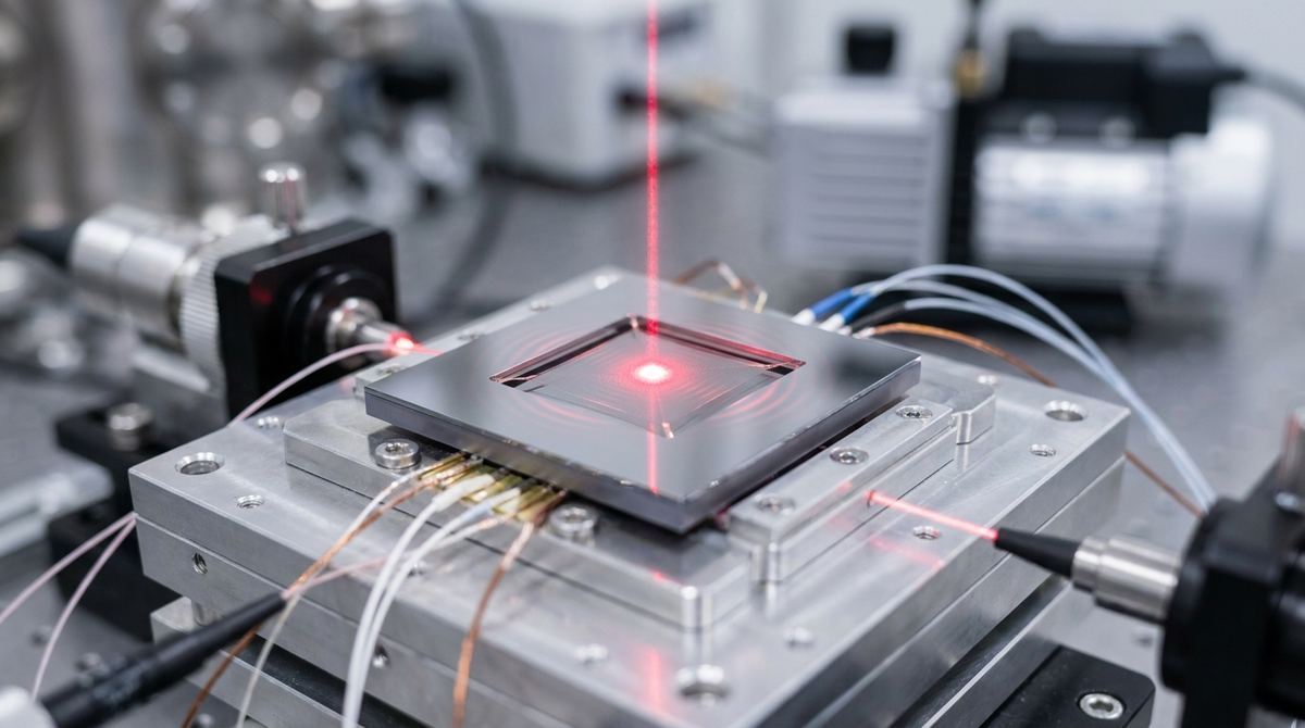
Graphene resonators are among the most sensitive mass sensors ever developed. Because graphene is only one atom thick, even a tiny change in mass—such as a single molecule landing on the surface—causes a measurable shift in the resonator's frequency. However, there is a major engineering hurdle: nonlinearity.
As a resonator vibrates with higher amplitudes, it enters a nonlinear regime, often described by the Duffing equation. In this state, the frequency of the resonator becomes dependent on its vibration amplitude. This leads to the jump phenomenon, where the resonance peak tilts and the signal suddenly "jumps" from one frequency to another. For an engineer building a mass sensor, this is a disaster. It makes the sensor unstable, limits the dynamic range, and makes it impossible to distinguish between a mass change and a change in vibration amplitude.
Recent research by Martín-Pérez, Steeneken, and Alijani provides a solution. They demonstrate that by using light to heat the graphene, we can actively tune the nonlinearity. By controlling the laser power, we can switch the resonator between hardening behavior (where frequency increases with amplitude) and softening behavior (where frequency decreases), or even suppress the nonlinearity entirely. This guide explains how to build a prototype that utilizes this effect for stable, high-sensitivity mass sensing.
The goal is to build a mass sensor that remains in a linear regime regardless of the vibration amplitude. By using an optical probe to tune the mechanical tension of the graphene, we can counteract the geometric nonlinearities that arise during high-amplitude oscillations. This allows for a much wider operating range and much higher precision in detecting mass loading.
You are building an optomechanical nano-electromechanical system (NEMS). The device consists of a single-layer graphene membrane suspended over a reflective cavity. An optical laser is used to provide photothermal tuning, and the mechanical vibrations are detected via the same optical path.
The following list includes the core components. Note that several values are engineering assumptions based on typical laboratory setups, as the source research does not provide specific dimensions.
1. Graphene: Monolayer CVD-grown graphene. This is typically transferred from a copper substrate to the target substrate using a PMMA-assisted method.
2. Substrate: A silicon wafer with a 300nm silicon dioxide (SiO2) layer.
3. Reflective Cavity: A trench etched into the silicon substrate. The bottom of the trench must be coated with a reflective material, such as 50nm of Gold (Au) or Aluminum (Al), to create an optical cavity.
4. Laser Source: A continuous-wave (CW) laser. A wavelength in the 532nm or 633nm range is recommended for effective photothermal interaction.
5. Detection System: A high-speed photodiode or a quadrant photodiode to monitor the reflected light.
6. Vacuum System: A vacuum chamber capable of reaching at least 10^-3 Torr. High vacuum is essential to minimize air damping and achieve a high Quality (Q) factor.
7. Control Electronics: A signal generator and a power meter to control and monitor the laser intensity.
1. Substrate Preparation: Use Reactive Ion Etching (RIE) to etch trenches into the SiO2 layer of your silicon wafer. We assume a trench depth of approximately 500nm to 1um. This depth is critical for the optomechanical interaction described in the research.
2. Reflective Coating: Use E-beam evaporation to deposit a thin layer of gold at the bottom of the etched trenches. This ensures that the light reflected from the graphene membrane is captured effectively.
3. Graphene Transfer: Perform a standard PMMA-assisted transfer of CVD graphene over the trenches. The graphene must be suspended across the trench to form the resonator.
4. Optical Alignment: Mount the laser on a high-precision XYZ translation stage. The laser must be focused directly onto the center of the suspended graphene membrane.
5. Vacuum Integration: Place the entire assembly inside a vacuum chamber. Ensure there is an optical window to allow the laser to enter and the reflected light to exit.
To validate the prototype, follow these testing stages:
1. Baseline Characterization: With the laser turned off, perform a frequency sweep using a signal generator to find the natural resonance frequency of the graphene.
2. Nonlinearity Mapping: Gradually increase the laser power (start at 0mW and increase in 1mW increments). Observe the resonance peak. You should see the peak tilt (the Duffing effect). According to the research, you should be able to observe the transition between hardening and softening behavior by adjusting the laser power and the cavity depth.
3. Nonlinearity Suppression: Increase the laser power until the resonance peak becomes symmetric again. This is the point where you have successfully suppressed the geometric nonlinearity.
4. Mass Loading Test: Introduce a controlled amount of gas (such as Nitrogen or a specific target molecule) into the chamber. Measure the frequency shift. Compare the sensitivity and stability of the sensor when the laser is used to suppress nonlinearity versus when it is turned off.
The research by Martín-Pérez et al. establishes the fundamental physics, but several parameters must be managed by the engineer.
Assumptions:
- Laser Power: We assume a starting range of 1mW to 10mW. Higher power may be required depending on the graphene's absorption, but excessive power will cause damage.
- Cavity Depth: We assume a depth of 500nm to 1um. The exact depth is critical for the optomechanical coupling strength.
- Temperature: We assume the photothermal heating will raise the local temperature of the graphene by a few Kelvin, which is sufficient to tune the tension without melting the membrane.
Risks:
- Thermal Rupture: Graphene is extremely thin. If the laser power is too high, the membrane will burn through or rupture due to excessive thermal tension. Always start with very low power.
- Adhesion Failure: The thermal stress from the laser can cause the graphene to peel away from the edges of the trench.
- Vacuum Leaks: Any leak in the vacuum chamber will introduce air damping, which will mask the nonlinear effects you are trying to study.
Serious about B2B integration? Test our premium Pulsed Electrical Resistive Carbon Heating turbostratic graphene in your lab. 100g sample packs available now.
Explore More
New research provides a theoretical framework for calculating the lifetime and spectral function of topological heavy fermions, a key step for developing...

Learn to build a prototype strain-tunable magnetic device using graphene as a sacrificial layer to create freestanding MnPtGa membranes. This guide covers...

Researchers revisit a graphene, n-heptane, and permalloy system, observing apparent ideal diamagnetism at ambient conditions, a key property of superconductors.