
Understanding the Lifetime of Topological Heavy Fermions in Graphene Systems
New research provides a theoretical framework for calculating the lifetime and spectral function of topological heavy fermions, a key step for developing...
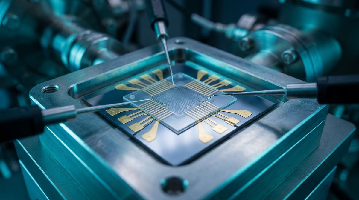
In high-precision sensing, we typically rely on classical electrostatics. When you change the distance between two conductive plates, the capacitance changes in a predictable, linear or near-linear fashion. However, as we push into the sub-nanometer regime, classical models begin to fail because they ignore the quantum mechanical energy required to add an electron to the system. This is known as quantum capacitance.
Recent theoretical research has identified a unique phenomenon in bilayer graphene that offers a massive opportunity for sensor design. While monolayer graphene follows standard electron-gas behavior, bilayer graphene exhibits an anomalous capacitance signature. Due to interband screening, the quantum capacitance correction in bilayer graphene is suppressed and, crucially, its sign reverses within experimentally relevant separation distances.
For an engineer, a sign reversal in a transducer signal is a powerful tool. It provides a unique, non-linear signature that can be used to distinguish a graphene-based sensor from classical capacitive noise or parasitic effects. This article outlines how to build a prototype sensor that exploits this anomalous quantum capacitance to detect ultra-small displacements.
To build this, you must understand why bilayer graphene is the chosen material. In a standard capacitor, the capacitance is determined by the geometry and the dielectric constant. In a quantum capacitor, the total capacitance is a combination of the geometric capacitance and the quantum capacitance. The quantum capacitance is directly related to the density of states and the energy cost of adding charge.
According to recent findings by Zverevich, Morpurgo, and Levchenko, the interlayer correlations in bilayer graphene create a Casimir-like effect. This effect is driven by zero-point fluctuations of the coupled plasmons in the bilayer. In monolayer graphene, these correlations follow a standard pattern. In bilayer graphene, however, the interband screening effects are so strong that they suppress the correction and flip the sign of the capacitance contribution.
This means that as you bring the two layers closer together, the capacitance will not follow the expected classical curve. Instead, it will exhibit a specific, anomalous shift. If you can measure this shift, you have a sensor that is sensitive to the quantum state of the electrons, allowing for displacement detection that is theoretically decoupled from many classical noise sources.
Building a device that can resolve these quantum effects requires extremely high-quality materials and precise fabrication. You cannot use standard industrial-grade graphene; you need high-mobility, low-defect samples.
Required Materials:
- Bilayer Graphene: Ideally exfoliated from high-quality graphite to ensure minimal defect density and high carrier mobility. Alternatively, high-quality CVD-grown bilayer graphene can be used for scaling, though signal-to-noise ratios will be lower.
- Hexagonal Boron Nitride (hBN): This is your dielectric spacer. It must be atomically smooth and extremely thin. We are targeting a thickness between 1 nanometer and 10 nanometers to ensure the interlayer correlations are measurable.
- Substrate: A highly doped silicon substrate with a thick thermal oxide layer (285nm or 300nm SiO2) to act as a back-gate.
- Electrodes: Gold and Titanium for electrical contacts. Titanium acts as an adhesion layer, and Gold provides high conductivity and chemical stability.
- Encapsulation: PMMA or a thin layer of hBN to protect the device from environmental contamination.
Assumptions for Prototype:
Since the exact separation required to observe the sign reversal is dependent on the specific carrier density, we assume a starting hBN thickness of 5 nanometers. We also assume the device will operate at temperatures below 77K (Liquid Nitrogen) to minimize thermal noise, although the paper suggests these effects may be observable at higher temperatures depending on the density.
The assembly of a bilayer graphene heterostructure requires a dry-transfer method, often referred to as the pick-and-place method, to prevent contamination.
1. Substrate Preparation: Clean the silicon/SiO2 substrate using a standard RCA cleaning process or oxygen plasma to ensure no organic residues remain.
2. hBN Depstrate: Deposit a thin layer of hBN onto the substrate using mechanical exfoliation or high-precision CVD deposition. For our target thickness, mechanical exfoliation of hBN flakes is preferred.
3. Graphene Pick-up: Using a polymer-based stamp (like PMMA), pick up a thin flake of bilayer graphene. The graphene must be placed directly on top of the hBN layer.
4. The Sandwich Method: Place a second, even thinner layer of hBN on top of the graphene. This creates the hraphene/hBN/graphene sandwich. This sandwich is then transferred onto the substrate.
5. Contact Patterning: Use Electron Beam Lithography (EBL) to define the contact areas. This is necessary because the features are too small for standard photolithography.
6. Metal Deposition: Deposit the Ti/Au layers using an electron-beam evaporator.
7. Final Encapsulation: To prevent the device from being affected by atmospheric moisture, encapsulate the entire structure with a final layer of hBN or a thin layer of PMMA that is subsequently etched away.
Once the prototype is assembled, the goal is to measure the capacitance-voltage (C-V) characteristics and identify the anomalous sign reversal.
1. DC Capacitance-Voltage (C-V) Profiling: Use a high-precision LCR meter or a Lock-in amplifier to measure the capacitance as a function of the gate voltage. The gate voltage will tune the carrier density in the graphene layers.
2. Frequency-Dependent Impedance Spectroscopy: Measure the capacitance across a range of frequencies (10 Hz to 1 MHz). Quantum capacitance effects are often frequency-dependent, and this will help distinguish the quantum signal from parasitic geometric capacitance.
3. Temperature Sweeps: Perform measurements from 300K down to 4K. The paper suggests that as you approach the exciton condensation or Wigner-crystal regimes, the capacitance becomes a probe of interlayer pairing. Observing the transition in capacitance behavior as temperature drops will validate that you are seeing the quantum effect.
4. Displacement Calibration: Use a piezo-electric actuator to vary the distance between the top layer and the substrate (if using a top-gate configuration) to correlate capacitance changes with physical displacement.
- Contamination: The biggest risk is trapped hydrocarbons between the layers. This will shift the Fermi level and mask the quantum capacitance. Mitigation: Perform all transfers in a nitrogen-filled glovebox and use vacuum-based cleaning steps.
- hBN Thickness Uniformity: If the hBN is too thick, the interlayer correlations will be too weak to detect. If it is too thin, the device may short-circuit. Mitigation: Use Atomic Force Microscopy (AFM) to verify the thickness of the hBN flakes before assembly.
- Signal-to-Noise Ratio: The quantum capacitance correction is described as being suppressed by orders of magnitude in bilayer graphene. Mitigation: Use a Lock-in amplifier for measurements to extract the tiny AC signal from the background noise.
- Carrier Density Control: The anomalous sign reversal is density-dependent. Mitigation: Ensure the back-gate and top-gate are highly stable to allow for precise tuning of the carrier density.
This guide is based on the theoretical framework provided by Zverevich et al. (2026) regarding the fluctuation electrodynamics of quantum capacitance. The application assumes that the theoretical prediction of sign reversal in the interlayer correction to the inverse capacitance can be translated into a measurable electrical signal in a physical device. We assume that the interband screening effects, which the authors identify as the cause for the anomalous behavior in bilayer graphene, can be successfully harnessed in a laboratory-scale prototype.
Serious about B2B integration? Test our premium Pulsed Electrical Resistive Carbon Heating turbostratic graphene in your lab. 100g sample packs available now.
Explore More
New research provides a theoretical framework for calculating the lifetime and spectral function of topological heavy fermions, a key step for developing...

Learn to build a prototype strain-tunable magnetic device using graphene as a sacrificial layer to create freestanding MnPtGa membranes. This guide covers...

Researchers revisit a graphene, n-heptane, and permalloy system, observing apparent ideal diamagnetism at ambient conditions, a key property of superconductors.