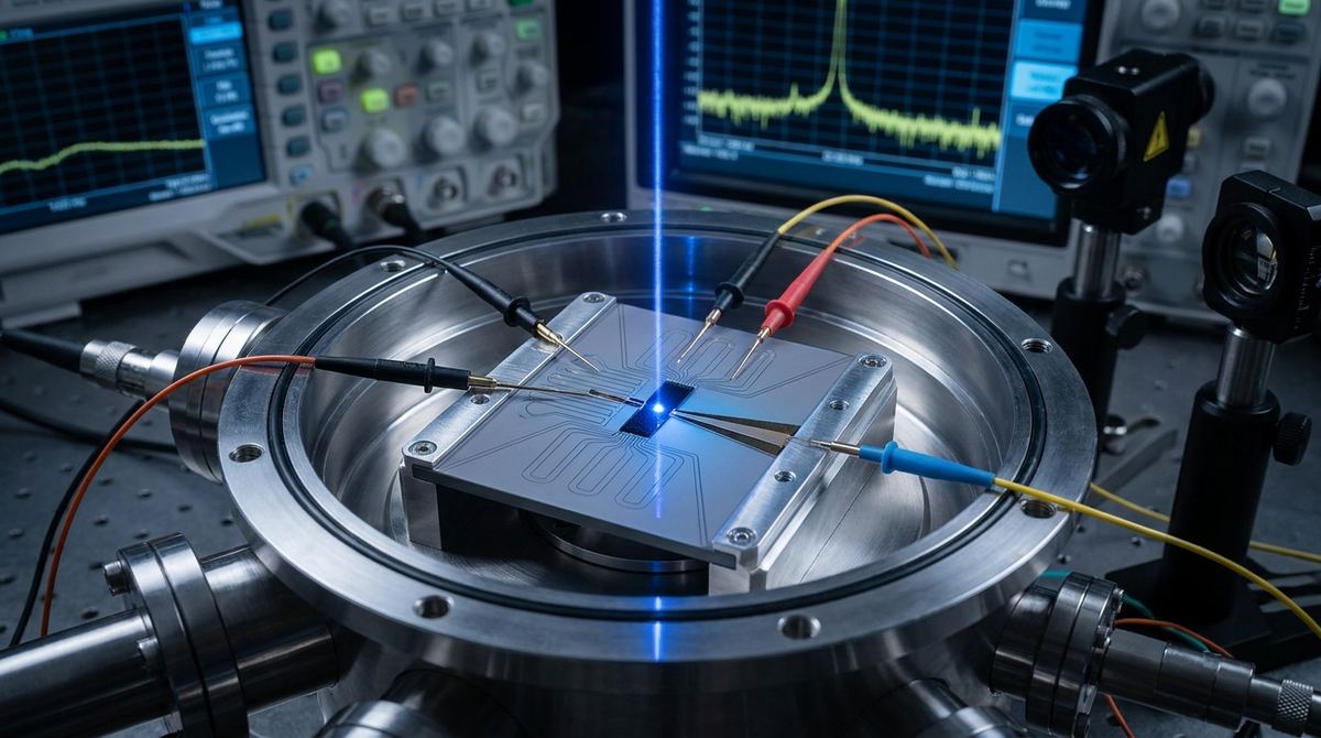
The Engineering Challenge of THz Detection
As wireless communication moves toward the 6G era, the demand for high-frequency signal monitoring is increasing. The D-band, which spans from 110 GHz to 170 GHz, is a critical frontier for ultra-high-speed data transmission. Historically, detecting signals in this terahertz (THz) range has been a major headache for engineers. Most existing solutions rely on hybrid flip-chip assembly, where discrete detector elements are mounted onto a waveguide. While functional, this method is problematic for scalable production. It results in poor mode coupling between the waveguide and the detector, a large physical footprint, and mechanical instability that can ruin signal consistency.
For a startup or a small lab developing next-generation wireless components, the goal is monolithic integration. This means the detector is built directly onto the silicon dielectric waveguide as part of the same manufacturing process. This guide outlines how to approach the construction of a room-temperature graphene-based detector integrated on a high-resistivity silicon waveguide, specifically designed for D-band operation. This approach allows for a much smaller footprint and more stable, integrated photonic circuits.
Required Materials and Component Specifications
To build a prototype based on the recent research, you cannot use standard silicon. You must use high-resistivity silicon (HR-Si) to minimize signal loss within the dielectric waveguide. The core of the detector is a graphene channel, but for high-performance operation, this graphene must be encapsulated.
1. Substrate: High-resistivity silicon (HR-Si) wafer. This is essential to ensure the THz waves propagate through the waveguide with minimal absorption.
2. Active Layer: A graphene-hBN sandwich. Hexagonal Boron Nitride (hBN) is used to encapsulate the graphene. This protects the graphene from environmental contaminants and, more importantly, provides an atomically smooth surface that preserves the high carrier mobility required for fast response times.
3. Coupling Element: A tapered slot-line antenna. This is typically patterned using gold or copper via electron-beam lithography (EBL). The antenna acts as the bridge that captures the guided mode from the silicon waveguide and concentrates it into the graphene channel.
4. Readout Interconnects: Gold or copper traces for electrical connection. Note that the length and geometry of these traces are critical, as they introduce parasitic inductance that can limit your device bandwidth.
Prototype Fabrication Workflow
Fabricating a monolithic graphene detector requires precision lithography and cleanroom environments. The following steps represent a standard engineering approach for this type of device.
Step 1: Substrate Preparation and Waveguide Definition.
Begin with a cleaned HR-Si wafer. You will need to define the dielectric waveguide structure on the silicon surface. This is typically achieved through etching or by using a high-resistivity layer that supports the guided mode.
Step 2: Graphene-hBN Stack Transfer.
Since high-quality graphene is often grown on copper and then transferred, you will use a dry transfer method. You will stack a thin layer of hBN, followed by a monolayer of graphene, and then a second layer of hBN. This sandwich is then transferred onto the silicon waveguide surface. The precision of this transfer determines the quality of the detector.
Step 3: Antenna Patterning.
The tapered slot-line antenna must be patterned directly onto the silicon surface, overlapping the graphene channel. This is best achieved using electron-beam lithography (EBL) to ensure the sub-micron precision required for D-band frequencies. Once patterned, a thin layer of gold is deposited via evaporation to form the antenna.
Step 4: Contact Formation.
Electrical contacts must be established to allow for the readout of the detected signal. These contacts connect the graphene channel to the external readout circuit. It is vital to keep these leads as short as possible to minimize parasitic inductance.
Step 5: Final Encapsulation and Passivation.
Ensure the entire active area is protected from oxidation to maintain the responsivity of the device over time.
Testing and Performance Verification
Once the prototype is fabricated, you must verify its performance in the D-band (110-170 GHz).
1. Frequency Sweep: Use a Vector Network Analyzer (VNA) equipped with frequency extenders to sweep the 110-170 GHz range. You are looking for the coupling efficiency of the antenna to the graphene channel.
2. Responsivity Measurement: To measure the voltage responsivity (V/W), apply a known, calibrated THz power to the waveguide and measure the resulting DC voltage across the graphene channel. Based on recent research, you should aim for a responsivity in the range of 11.5 V/W.
3. Bandwidth Testing: Measure the 3 dB bandwidth by observing the signal response over time or frequency. A key performance metric is the bandwidth of the readout. If your bandwidth is significantly lower than the intrinsic graphene response, your issue is likely the parasitic inductance in your interconnects, not the graphene itself.
Engineering Assumptions and Critical Risks
It is important to distinguish between the results provided by the research and the assumptions required for a practical build.
The research provides a specific performance benchmark: 11.5 V/W responsivity and a 1.94 GHz bandwidth at room temperature. However, the research does not provide the exact lithography dosages, the specific thickness of the hBN layers, or the exact chemical etching recipes used for the silicon waveguide. For a practical build, we assume an hBN thickness of approximately 5 to 20 nm and standard electron-beam lithography parameters for the gold antenna.
There are three primary risks to consider:
Risk 1: Parasitic Inductance. The research notes that the 1.94 GHz bandwidth is currently limited by the parasitic inductance of the readout interconnects. If your application requires higher bandwidth, you must focus heavily on the geometry of your gold traces and the impedance matching of your readout circuit.
Risk 2: Mode Coupling Efficiency. The efficiency of the tapered slot-line antenna in capturing the guided mode is highly sensitive to the alignment between the antenna and the waveguide. Even a few hundred nanometers of misalignment can significantly drop your responsivity.
Risk 3: Encapsulation Integrity. If the hBN encapsulation is not perfectly sealed or if there are air gaps in the stack, the graphene mobility will drop, and the device may fail to operate at room temperature or may exhibit high noise levels.
Source Basis
This guide is based on the research findings of A. Titchenko, K. Shein, M. Titova, M. Kashchenko, O. Popova, R. Izmaylov, E. I. Titova, I. Gayduchenko, and G. Goltsman, as published in the paper Room-temperature graphene sub-terahertz detector integrated on a silicon dielectric waveguide. The technical parameters, including the D-band operating frequency and the responsivity metrics, are derived directly from this source.