
Probing 2D Metals: Unlocking Electronic Secrets with Raman Spectroscopy
Researchers reveal how breaking inversion symmetry in 2D metals enables electronic Raman scattering, a powerful, non-destructive tool for characterizing...
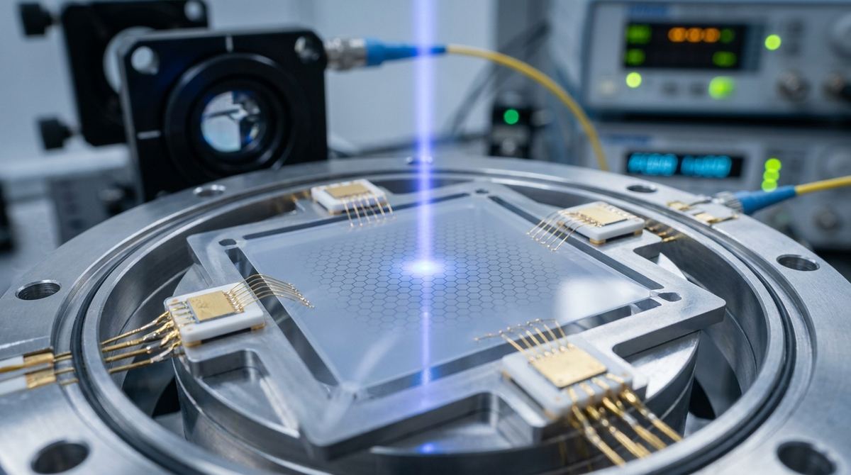
In the pursuit of ultra-stable timing and high-resolution sensing at the micro-scale, traditional MEMS (Micro-Electro-Mechanical Systems) often struggle with frequency drift and environmental sensitivity. A new frontier in this field involves hybridizing materials to exploit quantum-like interference phenomena. Specifically, the combination of a high-quality factor (Q) silicon nitride (SiNx) resonator with a low-quality factor graphene layer allows for the observation of Fano resonances.
Fano resonance occurs when a discrete, sharp resonance mode interferes with a broad, continuous background mode. In this hybrid architecture, the SiNx modes act as the sharp, discrete states, while the graphene mode provides the broad continuum. By applying a DC gate voltage, an engineer can tune the detuning between these modes, effectively controlling the asymmetry of the resonance. Furthermore, when driven into the nonlinear Duffing regime, the graphene mode can be frequency-locked to the SiNx modes, creating a stable, quantized frequency staircase. This guide outlines how to approach the development of a prototype device capable of acting as a nanomechanical frequency reference.
To build a practical device, you must understand the two operational regimes described in recent research.
In the linear regime, the device acts as a tunable Fano interferometer. By adjusting the DC gate voltage, you change the phase of the graphene continuum response. This allows you to switch the sign and magnitude of the Fano asymmetry parameter, q. For an engineer, this means you can design a sensor where the resonance peak can be flipped or sharpened purely through electrical control, providing a highly sensitive method for detecting minute changes in mass or force.
In the nonlinear regime, the device becomes a frequency ruler. When the drive power is increased, the graphene resonator enters the Duffing regime, where its oscillation becomes nonlinear. In this state, the graphene oscillation frequency does not drift freely; instead, it locks to the successive, stable modes of the SiNx membrane. This produces a staircase of drive-insensitive frequency plateaus. This is the key to creating a stable frequency reference: even if the drive power fluctuates, the resonator stays locked to the stable SiNx frequency.
To prototype this system, you will need high-precision microfabrication capabilities. The following materials are required:
1. Silicon substrate with a thick thermal oxide layer (SiO2) to serve as the base.
2. Silicon Nitride (SiNx) for the high-Q resonator membranes.
3. Chemical Vapor Deposition (CVD) grown graphene for the continuum mode.
4. Gold (Au) and Titanium (Ti) for electrical contacts and gate electrodes.
5. A DC voltage source for gate tuning (0 to 10V range assumed).
6. An AC signal generator for driving the resonator.
7. A high-sensitivity detection system, such as an electrical impedance analyzer or an optical interferometer.
Because this device relies on the interaction between two distinct mechanical modes, fabrication precision is critical.
1. Membrane Fabrication: Use a standard surface micromachining process to create suspended SiNx membranes on the silicon substrate. The membranes should be thin enough to allow for high-Q mechanical oscillations but robust enough to support the graphene layer. We assume a membrane size in the range of 10 to 50 micrometers for a starting prototype.
2. Graphene Transfer: Use the PMMA-assisted transfer method to deposit a single layer of CVD graphene over the suspended SiNx membranes. The graphene must be continuous and have minimal wrinkles to ensure the continuum mode is well-defined.
3. Electrode Patterning: Use photolithography and electron-beam evaporation to deposit Ti/Au electrodes. You will need contacts for the graphene layer and a dedicated gate electrode underneath the membrane (separated by a thin dielectric layer) to allow for DC voltage tuning.
4. Release Process: Perform a final etch to ensure the SiNx membranes are fully suspended and the graphene is free to vibrate.
5. Electrical Integration: Connect the device to an impedance analyzer to monitor the mechanical response through the graphene's electrical resistance changes.
Once the prototype is assembled, follow this testing protocol to verify the Fano and locking phenomena.
1. Linear Regime Characterization: Apply a small AC drive signal and sweep the frequency. Look for the characteristic asymmetric Fano resonance peak. Once identified, vary the DC gate voltage and observe the change in the asymmetry parameter, q. The goal is to demonstrate that the resonance shape can be tuned electrically.
2. Nonlinear Regime Characterization: Gradually increase the amplitude of the AC drive signal. Monitor the frequency response as the graphene mode enters the Duffing regime. You should observe the frequency response "jumping" to the nearest SiNx mode.
3. Frequency Locking Verification: Once the jump occurs, increase the drive power further. If the device is working correctly, the frequency should remain "locked" to the SiNx mode, creating a plateau on your frequency-vs-drive plot.
4. Stability Testing: Introduce a small "seeding tone" near the SiNx frequency to see if you can deterministically switch the resonator between adjacent locked states. This confirms the device can be used as a switchable frequency reference.
Since this is a laboratory-scale concept, several parameters must be assumed for the initial prototype:
1. Dimensions: We assume SiNx membranes of 10-50 micrometers. Smaller membranes will increase frequency but may decrease the signal-to-noise ratio.
2. Voltage: We assume a DC gate voltage range of 0 to 10V. Higher voltages may be required depending on the dielectric thickness, but exceeding 10V may risk dielectric breakdown.
3. Temperature: While the physics holds at room temperature, the quality factor (Q) will be significantly higher at cryogenic temperatures. For a practical startup prototype, we assume room temperature operation with a focus on the frequency locking stability rather than absolute Q-factor.
4. Drive Power: The transition to the Duffing regime is power-dependent. We assume a drive range from micro-watts to milliwatts.
1. Fabrication Complexity: The primary risk is the successful transfer of graphene onto a suspended membrane without tearing or contamination. Mitigation: Use high-quality CVD graphene and optimize the PMMA transfer process with controlled humidity and temperature.
2. Thermal Drift: Mechanical resonators are sensitive to temperature. Mitigation: Implement a thermal stabilization chamber or use the frequency-locking mechanism to compensate for thermal shifts.
3. Signal-to-Noise Ratio: At the micro-scale, the mechanical signal in the graphene's resistance can be very small. Mitigation: Use lock-in amplification techniques during the measurement phase to extract the signal from the noise.
4. Membrane Tension: Inconsistent tension in the SiNx membrane will lead to unpredictable resonance frequencies. Mitigation: Use standardized PECVD (Plasma Enhanced Chemical Vapor Deposition) processes to ensure uniform membrane stress.
This guide is based on the research findings of Rathi et al. (2026) regarding Fano resonances and frequency locking in graphene-SiNx hybrid nanomechanical systems. The application of the Duffing regime for frequency quantization and the use of SiNx as a frequency ruler are direct implementations of the theoretical models presented in the source material.
Serious about B2B integration? Test our premium Pulsed Electrical Resistive Carbon Heating turbostratic graphene in your lab. 100g sample packs available now.
Explore More
Researchers reveal how breaking inversion symmetry in 2D metals enables electronic Raman scattering, a powerful, non-destructive tool for characterizing...

Researchers use AI to accelerate the discovery of new materials, identifying a graphene-boron nitride composite for interstellar spacecraft shielding.

In BN-encapsulated graphene, the ultimate limit on electron speed is not graphene itself, but remote phonon scattering from the insulating layers that...