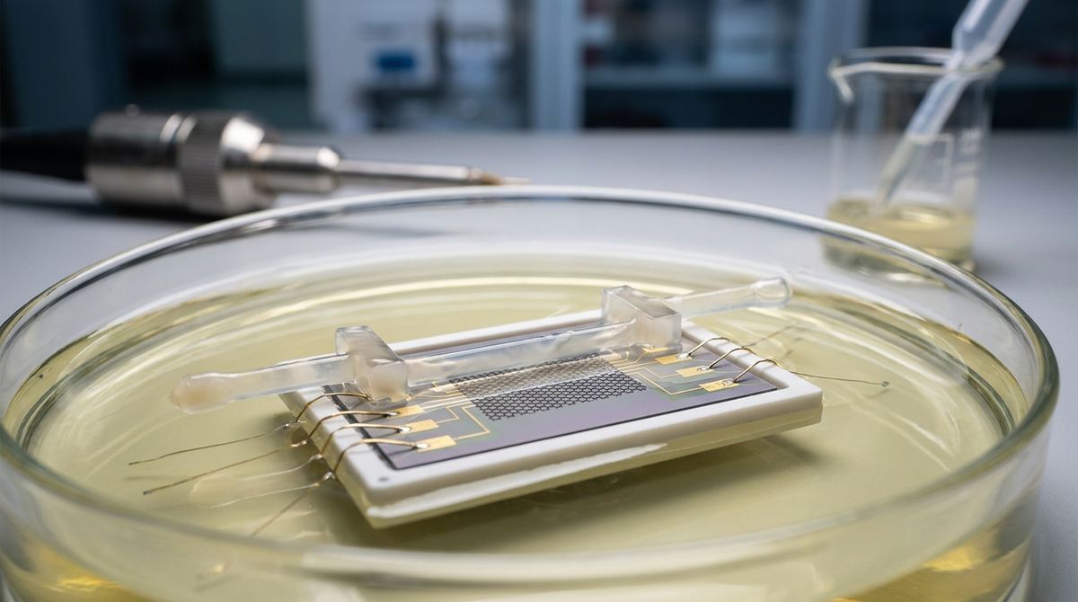
Introduction to HSA Sensing with Graphene EGFETs
Human Serum Albumin (HSA) is a critical biomarker in clinical diagnostics. Because it is the most abundant protein in human blood, its concentration levels are primary indicators for monitoring renal and hepatic disorders. For engineers and biotech startups, the challenge has always been creating a sensor that is both sensitive enough for early diagnosis and stable enough for real-time monitoring.
Traditional electrochemical sensors often rely on Faradaic processes, which involve redox reactions that consume the analyte and can lead to electrode fouling or device degradation. This guide focuses on building an Electrolyte-Gated Field-Effect Transistor (EGFET) using graphene. Based on recent research, this approach uses non-Faradaic operation, meaning the sensor detects the protein through electrostatic changes in the electric double layer (EDL) without consuming the sample. This allows for reversible, real-time sensing, which is essential for continuous monitoring applications.
The Physics of the Electric Double Layer (EDL) Mechanism
To build this device, you must understand how the signal is generated. When graphene is placed in an electrolyte (like a saline buffer), an electric double layer forms at the interface. This layer acts like a high-capacitance capacitor.
When negatively charged HSA molecules adsorb onto the graphene surface, they induce a change in the local electrostatic potential. Because HSA is negatively charged at physiological pH, its adsorption causes p-type doping in the graphene channel. This shifts the Dirac voltage—the point where the graphene conductance is at its minimum. By monitoring this voltage shift, you can quantify the concentration of HSA in the liquid.
The research highlights an interesting phenomenon: disorder-enhanced carrier scattering. In engineering terms, this means that slight imperfections in the graphene or the interface can actually amplify the signal, making the device more sensitive to small protein concentrations. However, this also means your device will be highly sensitive to environmental noise, requiring careful shielding.
Required Materials and Components
To prototype this device, you will need the following components. Note that some specifications are engineering assumptions based on standard laboratory practices.
1. Substrate: A silicon wafer with a thick thermal oxide layer (SiO2/Si, typically 285 nm or 300 nm). This serves as the base for the transistor.
2. Graphene: Chemical Vapor Deposition (CVD) grown graphene is recommended for scalability and uniformity. While exfoliated graphene offers higher mobility, CVD graphene is much more practical for a startup or small lab looking to scale production.
3. Electrodes: Gold (Au) with a thin Titanium (Ti) or Chromium (Cr) adhesion layer. These will serve as the Source and Drain electrodes.
4. Electrolyte: Phosphate Buffered Saline (PBS). We assume a 1x concentration at pH 7.4 to mimic physiological conditions.
5. Reference/Gate Electrode: A silver/silver chloride (Ag/AgCl) electrode is the standard for stable liquid-gating.
6. Microfluidic Housing: A Polydimethylsiloxane (PDMS) layer to create a channel for the liquid sample to flow over the sensor.
7. Measurement Electronics: A high-resolution source measure unit (SMU) capable of performing sub-volt sweeps and measuring nano-ampere level currents.
Prototype Fabrication Workflow
The following steps outline the assembly of a functional EGFET prototype.
1. Substrate Preparation: Clean the SiO2/Si substrate using a standard RCA cleaning process or a Piranha etch to ensure all organic contaminants are removed.
2. Graphene Transfer: Use a polymer-assisted transfer method (like PMMA) to deposit the CVD graphene onto the cleaned substrate. Ensure the graphene coverage is uniform across the intended channel area.
3. Electrode Patterning: Use photolithography or electron-beam lithography to define the Source and Drain electrodes. Sputter or thermally evaporate the Ti/Au layers. A channel length of 10 to 50 micrometers is a good starting point for high-sensitivity devices.
4. Microfluidic Integration: Bond a PDMS block containing a microfluidic channel onto the substrate. The channel should be positioned directly over the graphene channel to ensure the sample is in constant contact with the sensing area.
5. Electrical Interconnects: Connect the Source and Drain electrodes to your measurement setup via wire bonding or conductive epoxy. Connect the Ag/AgCl electrode to the gate/reference terminal.
6. Device Encapsulation: Ensure all electrical connections are sealed from the liquid to prevent short circuits, leaving only the graphene channel exposed to the fluid.
Testing and Calibration Protocol
Once the prototype is assembled, follow this testing plan to validate the HSA detection capabilities.
1. Baseline Establishment: Submerge the device in a pure PBS buffer. Apply a small sub-volt gate voltage (assume a range of -0.5V to +0.5V) and perform a conductance sweep to identify the initial Dirac voltage.
2. Concentration Gradient Testing: Introduce HSA solutions in increasing concentrations. Based on the research, you should test a range from 0.01 mg/mL to 10 mg/mL to capture the linear dynamic range.
3. Data Acquisition: For each concentration, record the shift in the Dirac voltage (the voltage at which minimum conductance occurs).
4. Sensitivity Analysis: Calculate the sensitivity by determining the change in Dirac voltage per unit of concentration (mV / (mg/mL)).
5. Reversibility and Stability Test: After each measurement, flush the channel with pure PBS to wash away the adsorbed proteins. Check if the Dirac voltage returns to the baseline. A successful device should show reversible behavior, allowing for multiple uses.
Engineering Assumptions and Technical Risks
Because this is a guide for a prototype, you must account for several variables that the research assumes or leaves to the designer.
Assumption 1: Electrolyte Concentration. The research implies a standard physiological buffer. For your prototype, use 1x PBS. Changing the ionic strength will drastically change the EDL capacitance and the signal magnitude.
Assumption 2: Gate Voltage. The research specifies sub-volt operation. For testing, start with a very narrow sweep of -0.5V to +0.5V to avoid water electrolysis, which would ruin the sensor and the sample.
Assumption 3: Temperature. Protein adsorption is temperature-sensitive. We assume a controlled room temperature (approx. 25 degrees Celsius). For clinical applications, you would need to stabilize the device at 37 degrees Celsius.
Risk 1: Biofouling. Even with non-Faradaic operation, proteins can stick to the electrodes or the PDMS walls, causing drift. You may need to treat the surface with PEG (polyethylene glycol) to reduce non-specific binding.
Risk 2: Signal-to-Noise Ratio. As mentioned, the disorder-enhanced scattering amplifies the signal but also increases noise. You will likely need high-precision, low-noise amplifiers and significant digital filtering to extract a clean signal from the conductance fluctuations.
Risk 3: Graphene Quality. The sensitivity is highly dependent on the graphene's electronic properties. Variations in CVD growth quality can lead to inconsistent Dirac voltage shifts across different devices.
Source Basis and Research Context
This guide is based on the research findings presented in the paper: Graphene Electric Double-Layer Transistors for Enhanced-Sensitivity Label-Free Detection of Human Serum Albumin, published in July 2026. The core technical data, including the limit of detection (0.0087 mg/mL) and the linear range (up to 10 mg/mL), is derived directly from the study's experimental results. The simulation insights regarding Brownian Dynamics and van der Waals interactions provide the theoretical foundation for why the protein adheres to the surface in specific orientations.