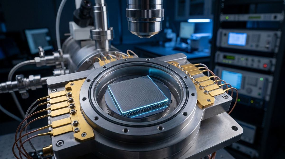
The Engineering Opportunity
Current semiconductor technology is approaching physical limits regarding heat dissipation and scaling. The next frontier in low-power, high-speed electronics lies in topology. Specifically, topological insulators offer the promise of dissipationless transport via edge states, where electrons flow without scattering, significantly reducing energy consumption.
Recent research has identified a specific way to engineer these states using van der Waals heterostructures. By stacking twisted double bilayer graphene (TDBG) with a transition-metal dichalcogenide (TMDC) like WSe2, we can use the crystallographic alignment angle as a primary control knob. This allows us to switch a device between a Chern insulator state (which has topological properties) and a trivial insulator state (which does not). For an engineer or a startup, this represents a blueprint for a topological transistor: a device where the fundamental topological character of the material is toggled by controlling the alignment of the layers.
The Core Mechanism: Twist-Angle Tuning
The ability to switch states relies on the competition between two types of spin-orbit coupling (SOC): Ising SOC and Rashba SOC.
When the graphene layers and the WSe2 layer are perfectly aligned (0 degree twist), the Ising SOC dominates. This creates flat bands with finite valley Chern numbers, resulting in a Chern insulator state. In this state, the material exhibits quantized Hall resistance, making it a candidate for topological logic.
As the twist angle between the graphene and the WSe2 increases (for example, to 15 degrees), the Rashba SOC becomes the dominant force. This reshapes the band topology, resulting in topologically trivial bands (C = 0).
By controlling this angle during the fabrication process, or potentially through mechanical strain in a finished device, we can create a switch that moves from a topological conductor/insulator to a standard insulator.
Required Materials and Equipment
Building a prototype of this device requires high-precision nanofabrication capabilities.
1. High-quality Bilayer Graphene (BLG): Must be exfoliated or grown via CVD with extremely high mobility.
2. WSe2 (Tungsten Diselenide): A high-quality flake of WSe2 is required to provide the necessary proximity-induced spin-orbit coupling.
3. Hexagonal Boron Nitride (hBN): Used for encapsulation to protect the active layers and maintain high carrier mobility.
4. Substrate: Silicon/Silicon Dioxide (Si/SiO2) or a specialized sapphire substrate.
5. Contact Metals: Gold (Au) and Titanium (Ti) for electrical connections.
6. Fabrication Equipment:
- A high-precision rotation stage (capable of 0.1 degree accuracy) for the stacking process.
- Electron-beam lithography (EBL) system for fine-patterning contacts.
- Thermal evaporation or e-beam evaporator for metal deposition.
- A dry-transfer setup using polymers like PC (Polycarbonate) or PDMS.
- A cryogenic measurement system (Dilution refrigerator or He-3 cryostat) capable of reaching sub-Kelvin temperatures.
Prototype Construction: The Topological Hall Bar
To test the topological switching capability, the most effective geometry is a Hall bar. This allows for simultaneous measurement of longitudinal resistance (Rxx) and Hall resistance (Rxy).
Step 1: Exfoliation and Preparation
Exfoliate thin flakes of WSe2, graphene, and hBN onto a substrate. Use an optical microscope to identify flakes of the desired thickness. For this application, the graphene must be a high-quality bilayer.
Step 2: The Stacking Sequence (Critical Step)
The order of stacking is vital. The recommended stack is:
Substrate / hBN / WSe2 / Twisted Double Bilayer Graphene / hBN.
The twist angle must be controlled during the transfer. Using a dry-transfer method, pick up the WSe2 flake first, then the graphene stack. Use a high-precision rotation stage to set the angle between the graphene lattice and the WSe2 lattice. To demonstrate the switch, you must create two separate devices: one with 0 degrees alignment and one with 15 degrees alignment.
Step 3: Encapsulation
Encapsulate the active layers with hBN. This prevents environmental contamination and ensures that the electronic properties are dominated by the internal SOC rather than external impurities.
Step 4: Contact Patterning
Use electron-beam lithography to define the Hall bar geometry. Pattern the contact pads using a resist, then deposit Ti/Au via evaporation. Ensure the contacts are placed on the graphene layers to allow for electrical transport measurements.
Step 5: Gate Integration
To reach the specific "quarter filling" state mentioned in the research, you will need a back-gate (the Si substrate) or a top-gate (an additional hBN/metal layer) to tune the carrier density.
Testing and Validation Protocol
The goal is to confirm the presence of the Chern insulator state at 0 degrees and its absence at 15 degrees.
1. Cryogenic Cooling: Place the device in a cryostat. The research suggests these correlated states are observable at very low temperatures. We assume a starting testing range of 50mK to 4K.
2. Carrier Density Tuning: Use the gate voltage to tune the carrier density toward the quarter-filling point. This is where the correlated insulating behavior is most prominent.
3. Transport Measurements:
- Measure the longitudinal resistance (Rxx) and the Hall resistance (Rxy) as a function of the magnetic field and gate voltage.
- For the 0-degree device: Look for a quantized Hall plateau where Rxy = h/e^2 (or an integer multiple) and Rxx approaches zero. This confirms the C = +1 Chern insulator state.
- For the 15-degree device: You should observe insulating behavior (increased Rxx) due to correlation, but the Hall resistance (Rxy) should not show the same quantized topological plateau, indicating a C = 0 trivial state.
4. Data Comparison: Compare the Rxy values of the two devices. The sharp contrast in the Hall response, despite both devices being in an insulating regime, validates the topological switching mechanism.
Engineering Assumptions and Critical Risks
This guide is based on the theoretical and experimental findings from the source research. However, several engineering assumptions must be acknowledged:
1. Temperature Assumption: The research does not specify the exact temperature for the 15-degree device, but correlated states in graphene typically require millikelvin temperatures. We assume a dilution refrigerator is mandatory.
2. Twist Angle Precision: The research relies on the distinction between 0 and 15 degrees. In a practical lab setting, achieving a precise 0-degree alignment (crystallographic alignment) is extremely difficult. Any misalignment will introduce Rashba SOC and could degrade the Chern state.
3. Carrier Density Assumption: The research specifies "quarter filling." In a real device, the exact density depends on the specific geometry and gate capacitance. Engineers must assume a wide-range sweep of gate voltage is required to find the target density.
4. Material Purity Risk: The entire effect relies on the interplay between SOC and electron-electron correlations. Any significant impurity concentration or lattice strain from the transfer process will likely destroy the delicate topological states.
5. Scaling Risk: While this demonstrates a fundamental switch, scaling this to a multi-gate integrated circuit is a significant challenge, as it requires precise control over the twist angle across an entire wafer.
Source Basis: This guide is derived from the research "Orientation-tunable correlated Chern insulating states in chiral twisted double bilayer graphene proximitized by WSe2" (Xie et al., 2026).