Practical Guide: Engineering High-Flux Nanofiltration: Leveraging hBN Asymmetry for Enhanced Water Transport
Introduction
The global water crisis is driving a massive shift in membrane technology. Traditional desalination and nanofiltration methods often struggle with the trade-off between permeability (how fast water flows) and selectivity (how well it filters out contaminants). While graphene has long been the darling of the materials science community for its potential in water filtration, recent multiscale simulations suggest that we may have been looking at the wrong two-dimensional material for high-speed transport.
New research indicates that hexagonal boron nitride (hBN) may significantly outperform graphene in water transport efficiency. This is not due to the material's thickness or density, but rather due to the atomic-scale asymmetry of its pores. For engineers and startups working on next-generation water purification, this finding provides a new design roadmap: move away from symmetric, non-polar membranes like graphene and toward asymmetric, polar membranes like hBN to achieve higher water flux.
The Physics of Enhanced Flow
To build a better membrane, we must understand why hBN behaves differently than graphene at the nanoscale. According to recent multiscale simulations, graphene nanopores are symmetric and non-polar. When water molecules encounter a graphene pore, they exhibit a random distribution with no preferential orientation. This randomness creates a form of molecular friction, resisting the flow of water through the pore.
In contrast, hBN is a polar material. The asymmetry of hBN pores induces an electric dipole moment. This dipole moment creates a structured environment for water molecules. Instead of bumping around randomly, the water molecules are organized by the electric field of the pore, allowing them to slip through the membrane with much lower resistance. Essentially, hBN turns the nanopore into a molecular highway rather than a chaotic obstacle course.
The Application: High-Flux Nanofiltration
The most immediate practical application for this insight is the development of high-flux nanofiltration membranes. These membranes are used to remove divalent ions (like calcium and magnesium), heavy metals, and organic micropollutants from water.
By utilizing hBN-based membranes, engineers can design systems that require significantly less pressure to achieve the same filtration rate as current graphene or polyamide membranes. This translates directly to lower energy consumption in desalination plants and more efficient portable water purification units.
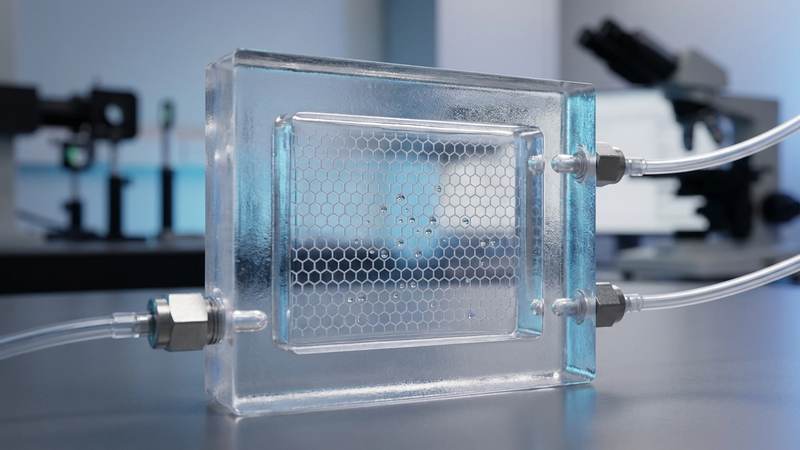
What to Build: A Microfluidic Filtration Prototype
For a small lab or a startup, the goal is not to manufacture industrial-scale rolls of hBN immediately, but to create a microfluidic testbed to validate the enhanced flux properties. You will build a microfluidic device that incorporates a thin-film hBN membrane to compare its performance against a graphene oxide (GO) control membrane.
Required Materials
To build this prototype, you will need the following:
1. Hexagonal Boron Nitride (hBN) nanosheets: High purity, ideally with a controlled lateral size.
2. Graphene Oxide (GO) nanosheets: To serve as the non-polar control group.
3. Polyethersulfone (PES) or Polyvinylidene fluoride (PVDF) support: A porous polymer substrate to provide mechanical strength to the 2D layers.
4. Polydimethylsiloxane (PDMS): For creating the microfluidic channels.
5. Glass microscope slides: To act as the base for the microfluidic device.
6. Syringe pump: For precise control of the flow rate and pressure.
7. Conductivity meter: To measure the salt rejection rate.
8. Vacuum filtration setup: To deposit the 2D layers onto the polymer support.
Prototype Fabrication Steps
Because creating sub-nanometer pores in hBN is a complex process, this guide assumes a two-stage approach: first, creating a dense hBN film, and second, using electrochemical etching or ion-beam milling to create the pores. For a small lab, it is more practical to start with pre-fabricated nanoporous hBN membranes if available, or use a chemical etching method.
Step 1: Preparation of the 2D Suspension
Disperse the hBN nanosheets in a high-purity solvent, such as isopropyl alcohol (IPA), using probe sonication. The concentration should be kept low (e.g., 0.1 to 0.5 mg/mL) to ensure a uniform, thin layer.
Step 2: Membrane Deposition
Use vacuum-assisted filtration to deposit the hBN suspension onto the PES support. The goal is to create a thin, continuous film of hBN that is only a few atomic layers thick. The thickness of the PES support should be approximately 10 to 50 micrometers to allow for rapid transport while maintaining structural integrity.
Step 3: Pore Creation (Engineering Assumption)
Since the research focuses on the effect of the pores, the pore size is critical. We assume a target pore diameter of 0.5 to 2.0 nanometers. In a lab setting, this can be achieved by controlled electrochemical etching in a fluoride-based electrolyte. This step is highly sensitive and requires precise voltage control.
Step 4: Microfluidic Integration
Cast a layer of PDMS over the hBN/PES membrane. Once cured, use a plasma cleaner to bond the PDMS to a glass slide, creating a sealed microfluidic channel. This channel will allow you to apply controlled pressure to the membrane.
Step 5: Control Group Preparation
Repeat steps 1 through 4 using Graphene Oxide (GO) instead of hBN. This will allow for a direct comparison between the polar (hBN) and non-polar (GO) transport mechanisms.
Testing and Validation Plan
To validate the research findings, you must measure two primary metrics: Water Permeability and Salt Rejection.
1. Permeability Testing:
Set up the microfluidic device in a closed loop. Use the syringe pump to apply a constant pressure (starting at a cautious range of 1 to 5 bar) and measure the volume of water passing through the membrane over time. Calculate the permeability (L/m2/h/bar). According to the source, the hBN membrane should show significantly higher permeability than the GO membrane.
2. Salt Rejection Testing:
Prepare a solution of Sodium Chloride (NaCl) at a concentration of 1000 ppm. Pass this solution through the membrane and measure the conductivity of the feed solution versus the permeate (the filtered water). The rejection rate is calculated as:
Rejection % = (1 - (C_permeate / C_feed)) 100
3. Stability Testing:
Run the system continuously for 24 to 48 hours to ensure the hBN layer does not delaminate from the PES support under constant pressure.
Engineering Assumptions and Risks
It is vital to distinguish between the simulation results and the physical implementation.
Assumption 1: Pore Uniformity. The research is based on simulations of single, well-defined nanopores. In a physical prototype, achieving a uniform distribution of 1nm pores across a square centimeter of membrane is an immense engineering challenge.
Assumption 2: Pore Size. The simulation results are highly dependent on the pore geometry. We have assumed a diameter of 0.5 to 2.0 nm. If the pores are too large, the selectivity will fail; if they are too small, the flux benefits of the dipole moment may be negated by steric hindrance.
Risk 1: Membrane Fragility. 2D materials like hBN are extremely thin. The mechanical stress of the microfluidic testing may cause the membrane to rupture.
Risk 2: Scaling. While hBN shows superior flow in simulations, the cost of high-purity hBN and the complexity of creating controlled nanopores may make it difficult to scale for mass-market water filtration compared to current polymer membranes.
Source Basis
This guide is based on the research paper "Water Flow Through Polar and Non-Polar Nanopores: Insights from Multiscale Simulations" by de Moraes et al. (2026). The core scientific insight—that hBN's asymmetry and induced dipole moment facilitate higher water flux compared to graphene's symmetric, non-polar pores—is taken directly from the study's QM and QM/MM simulation results. All fabrication steps, material choices, and testing protocols are engineering assumptions intended to translate these molecular-scale findings into a physical prototype.
Evaluate Our Quality
Serious about B2B integration? Test our premium Pulsed Electrical Resistive Carbon Heating turbostratic graphene in your lab. 100g sample packs available now.